Lesedi Project Wiki
- This wiki is for construction of a spectrograph on the 1-m Lesedi telescope in Sutherland. We anticipate future wikis for the user manual and for technical support.
- The SAAO and LJMU (Liverpool John Moores University) are collaborating on the project.
- The instrument is based on SPRAT (Spectrograph for Rapid Acquisition of Transients), which is currently operating robotically on the 2-m Liverpool Telescope on La Palma.
Project Team
Instrument PI: Iain Steele (LJMU; I.A.Steele@ljmu.ac.uk)
Instrument Scientists: Helen Jermak (h.e.jermak@ljmu.ac.uk)/ Andrjez Piascik (LJMU; A.S.Piascik@ljmu.ac.uk)
Mechanical Engineer: Stuart Bates (LJMU; S.D.Bates@ljmu.ac.uk)
Software Engineer: Chris Mottram (LJMU; C.Mottram@ljmu.ac.uk)
Data Pipeline: Marco Lam (LJMU; C.Y.Lam@ljmu.ac.uk)
Local Co-PIs: Nicolas Erasmus (nerasmus@saao.ac.za) & Hannah Worters (hannah@saao.ac.za)
Local Electronics Engineer: Hitesh Gajjar (hitesh@saao.ac.za)
Local Mechanical Engineers:James O'Connor (joc@saao.ac.za), Egan Loubser (egan@saao.ac.za), and Kathryn Rosie (krosie@saao.ac.za)
Local Software Engineer: Carel van Gend (carel@saao.ac.za)
Documentation
- The link to the 2017 October 27 Skype kick-off presentation: https://www.dropbox.com/s/lcr54nkvtusdh69/SAAO-SPRAT-KICKOFF.pptx?dl=0 (includes references to the SPIE paper and Zej's thesis)
Notes from meetings
31 Jan. 2019 Telecon with Iain, plus email communication
12 Feb. 2020 Filter requirement meeting (Nic, Hannah, Retha, James, (Kathryn))
SHOC/SPRAT hybrid
- Point was raised that (rather than comount SHOC and this new spectrograph) we could use an iXon camera in the SPRAT system, add filter wheels, and effectively use it as SHOC when the slit, grating, and prisms are out of beam. The iXon has 1024 x 13-micron pixels as opposed to the iDus 1024 x 26-micron pixels. A test was performed at LT in the week of 15 Dec., in which the 85 mm f/1.8 camera lens was swapped out with a 50 mm Nikon f/1.4. The result from an arc was 7.70 Å/channel, central wavelength 6009.04 Å, range 4073.64 – 8018.33 Å. This range could be tweaked by tilting the camera slightly.
Some more details 50mmLensTest
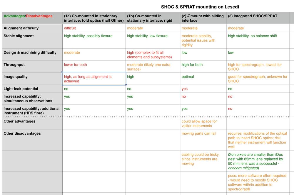
- Point raised by Stu at 12 Feb. 2019 Skype about filter wheel insertion into collimated beam causing flexture. James thinks that if the design can stay within the original structure envelope, and we are smart about orientation, the current stiffness might suffice. Alternatives to consider are (1) mounting a filter wheel near the entrance to the instrument or (2) separate SPRAT/SHOC mountings, by removing SPRAT and disconnecting the camera to reattach on the port.
Spreadsheet of pros/cons for proposed mounting options
Project Schedule
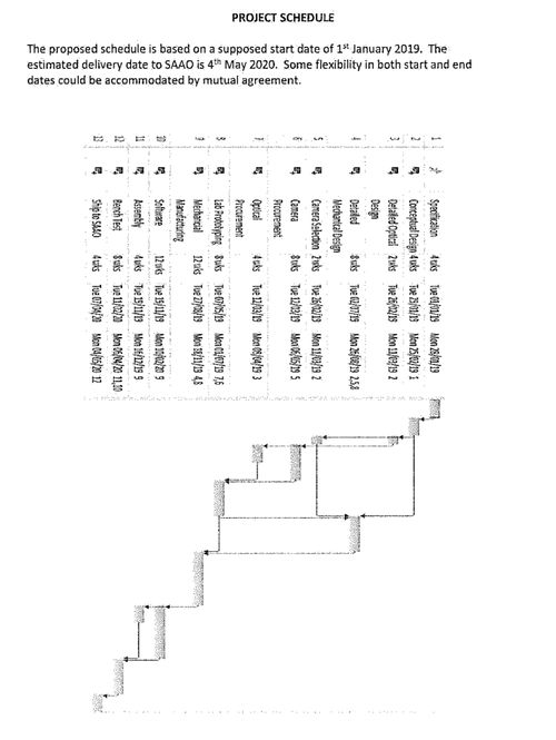
Proposed: start 01 Jan 2019, delivery 04 May 2020. See timeline in bid. Note that paperwork was not signed until 01 March 2019, so there is an anticipated delay.
Lens Coatings and Andor CCD
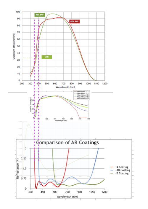
17 January 2020: Decision was made to go with Andor Ixon 888 UVB and -AB AR coating for lenses. Decision swayed by the off-the-shelf Nikon lens which will be the limiting element for obtaining spectra/photometry below 400nm. -A coating not good > 750nm where other elements still perform well.
Preliminary Exposure Time Calculator
Imaging Photometry Filters
Link below to the SDSS filters for Mookodi's imager:
Interfaces
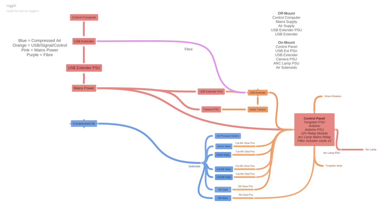
27 January 2020: Diagram showing overview of system interfaces.
Software
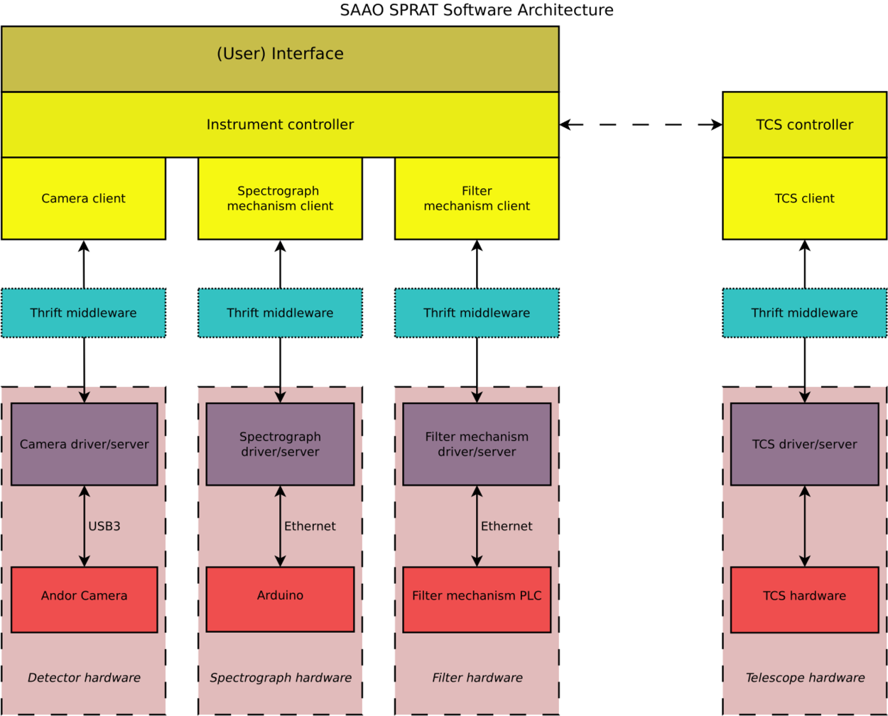
The software runs on an instrument PC, which hosts the camera driver software and connects to an Arduino for the moving parts. Additionally a filter mechanism may be controlled from here.
We envisage providing Thrift interfaces to the camera driver, the Arduino driver and the filterwheel driver. These all run as standalone server processes, and are accessed by an instrument controller process, which has clients for each of the server processes. The instrument controller contains logic to coordinate the instrument operations, and also is able to send commands to and receive state from the telescope.
The following diagram illustrates the software layout:
Software Interfaces
Detector
Moving parts
Data Files
The camera driver software retrieves the observation data from the camera, converted this to FITS format and saves this to disk.
The FITS files are named according to the SAAO file naming convention:
FITS header fields
The FITS headers include the keywords:
