SHOC
Contents
SHOC User Manual
NOTE: THIS PAGE REFERS TO THE LINUX- and WEB-BASED SOFTWARE (AS OF MARCH, 2015). For the original, manufacturer-based software and instrument commissioning details, please refer to the manual at http://shoc.saao.ac.za/Documents/ShocnHelpful.pdf.
Introduction
The SHOC systems consist of a filterwheel unit (with one or two filterwheels), a GPS unit for providing accurate timing triggers, an Andor iXon camera, and a control PC. Currently there are 2 production, and 1 development computer systems that go with the SHOC instrument. There are 2 working Andor cameras.
The SHOC website may well have more extensive detail about this instrument.
Dr. Marissa Kotze has written some pipeline software which may help with reduction of SHOC data.
Quick Start
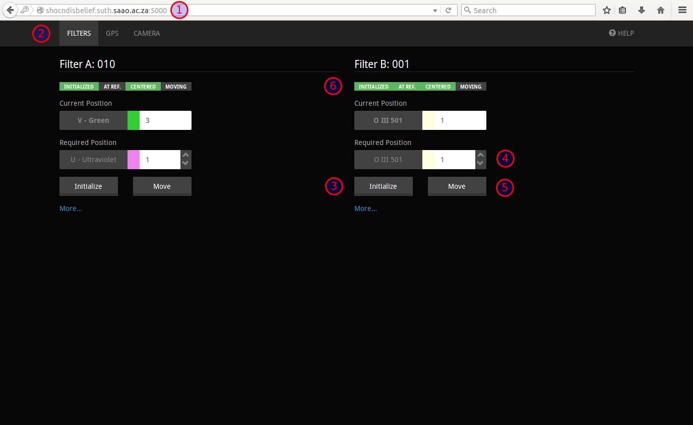
* Unlike the image below: at the telescope, the address is http://shocnawe.suth.saao.ac.za:5000 or http://shocndisbelief.suth.saao.ac.za:5000, depending on which system is mounted.
- Point your browser at http://<name>.suth.saao.ac.za:5000 (<name> is either shocnawe, or shocndisbelief). (1)
- Select the filterwheel tab (2).
- Initialize the filterwheel(s) (3), then select the filter required (4), click "Move" (5). The "Centered" indicator should be green when the wheel is finished moving (6).
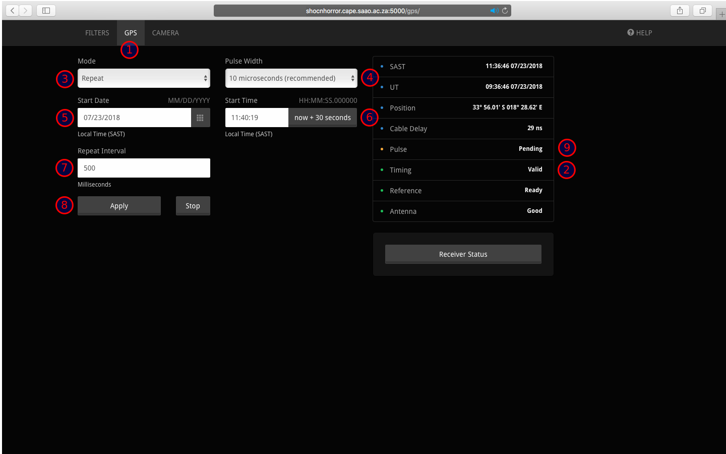
- If using external triggering, select the GPS tab (1)
- Ensure timing is valid (2).
- Set the Programmed Output Pulse (POP) parameters (mode (3), pulse width (4), start date (5), start time (6), trigger interval (7)) and click apply (8). The status should change to pending (9).
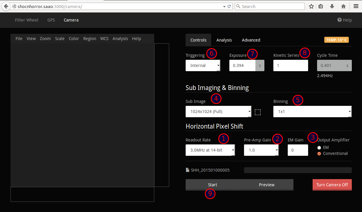
- Select the camera tab (1).
- Turn the camera on (2)
- Set the desired Readout Rate (1), Preamp (2) and Electron Multiplying (3) parameters (NB: EM MODE MAY ONLY BE SET IF YOU HAVE WRITTEN PERMISSION TO DO SO).
- Set the sub image (4) and binning (5) parameters.
- Set the trigger type (6), exposure (7) and kinetic series (8) parameters.
- Start the acquisition (9).
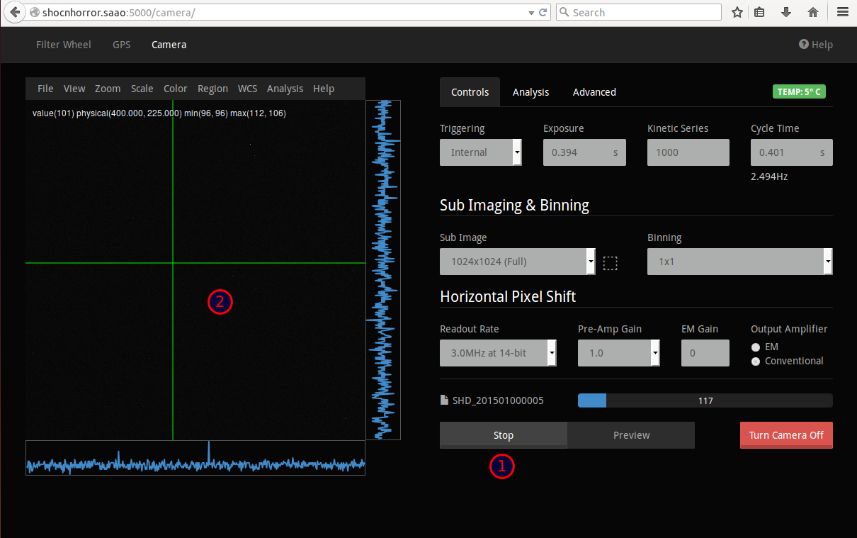
- Stop to abort (1), or wait until completion. The image display area (2) shows snapshots of the images throughout the acquisition.
- When the series is complete, the FITS data cube is copied to /data/<telescope>/<YYMM>/<filename>.fits, where <telescope> is 40in or 74in, YYMM is the year and month, and filename is the instrument abbreviation (SHA or SHD) followed by the date in YYYYMMDD format.
Advanced users guide
Web interface
- The primary means of controlling SHOC is via a web interface. The Firefox or Chrome browsers are preferred.
- Point your browser at http://<name>.suth.saao.ac.za:5000 (where name is the name of the SHOC instrument you're using; either shocnawe or shocndisbelief). For example, http://shocnawe.suth.saao.ac.za:5000
- The interface should appear, showing three tabs: Filterwheel, GPS and Camera.
Filter wheel
- Select the filterwheel tab. There may be one or two wheels physically present; the interfaces to these are displayed side-by-side. The interface values for a wheel will be empty if the wheel is absent.
- Initialize the wheel by clicking the "Initialize" button (usually only at the start of the night, but may also be done if you suspect that the controller has lost its way). The wheel will move around to the reference position; this may take several seconds. While still moving, the "Moving" indicator above the controls will be red. Once there, the "Initialized" and "At Ref" indicators should turn green. The value in the "Current Position" field should be 1 after initialization.
- Select the filter required, by using the up and down arrows on the right of the "Required Position" field. The filter name will indicate the filter in the selected position. Click the "Move" button. The indicators above the wheel controls should change; once the wheel has reached the required position, the "Moving" indicator should turn grey, while the "Centred" indicator should be green. The "Current Position" field will indicate the slot number and name of the filter now in the light path.
GPS
- The GPS tab allows the user to view the time, GPS state, and to change the Programmed Output Pulse (POP) settings.
- Check that the time is valid, and that there are no alarm conditions indicated.
- To set the Programmed Output Pulse, choose whether you want a single or repeating pulse, then choose a pulse width, the start date and time (in local time, 24 hour format), and for repeating pulses, the repeat interval. Then push the "Apply" button. Note: the POP may only be set to occur in the future; if an error occurs, check that you haven't chosen a time in the past.
- To stop the pulses from being sent, click the "Stop" button.
Camera
- The camera tab allows control and setting of the SHOC imaging camera.
- Before using the camera, you need to switch it on: click the "Turn Camera On" button.
- Once the camera has been initialized, the camera setting and view interface is displayed.
- On the left is the image display area; more on that later.
- On the right is the settings area, with three tabs for camera control, analysis and advanced settings.
- When switched on, the camera starts cooling to its target temperature. The temperature display button is orange while the camera is not yet at the target temperature, and green once it is. If using a non-standard temperature, this may be set using the "Advanced" tab.
- The camera may be used in internal, external or external start modes, selectable using the "Triggering" drop-down.
- While in internal or external start trigger modes, the exposure time may be set, and the kinetic cycle time is automatically calculated and displayed. The latter is the period between the start of successive frames in a kinetic series. Arbitrarily short exposre and kinetic cycle times are not possible, due to the time required to read out the image. If you choose an exposure time less than the minimum allowed, the minimum exposure and kinetic cycle times are calculated and automatically displayed.
- In external trigger mode, the kinetic cycle time is determined by the frequency of the GPS POP signals. However, this frequency should not be higher than than the minimum readout time. The minimum allowed kinetic cycle time is calculated and displayed; this may be useful when deciding on the GPS POP frequency to use.
- For all trigger modes, the number of frames in the data cube is determined by the Kinetic Series value.
- The next row down allows the sub-image area and binning to be chosen. For both of these, standard or custom values may be used. Smaller sub-images and higher binning allow faster image readouts, at the expense of image size and resolution. The minimum values discussed above are automatically re-calculated and displayed when the sub-image or binning is changed.
- Below this, the readout speed and preamp gain may be set. Higher readout speeds allow for shorter exposure times, but at the expense of noisier data.
- The last setting is the Electron Multiplying (EM) gain. NOTE: DO NOT USE ELECTRON MULTIPLYING MODE UNLESS YOU HAVE SPECIFICALLY OBTAINED PERMISSION FROM DR AMANDA GULBIS TO DO SO, AND YOU UNDERSTAND HOW AND WHEN TO USE IT. PERMANENT DAMAGE TO THE SENSOR CAN RESULT FROM INCORRECT USAGE. If you are using EM mode, choose the EM output amplifier, and then select a gain. BEGIN WITH LOW GAIN VALUES!
- To get a quick view of the images that will result, press the "Preview" button. Images will be displayed in the left-hand display panel. Press "Stop" when you're done.
- To begin collecting data, press the "Start" button. The kinetic series will start, either immediately or at the designated time if using the GPS, and the data will be spooled to disk. At the same time, temporary images will be displayed in the image display area.
- Once the acquisition is finished (or earlier, if you push the "Stop" button), the header information in the FITS cube will be updated to include various GPS, filter and environmental parameters, an the cube written to disk. The filename for the current or past kinetic series is displayed above the "Start" button. The filename consists of the instrument name, the date and an index. The index is updated every acquisition. and the new filename is calculated and displayed immediately after the "Start" button is pressed.
- The index appended to file names begins at 1, and increments by 1 after each acquisition. It may be edited by clicking on the "Advanced" tab, and changing its value. Note that if you change it to a value already used, it will cause files with that value to be overwritten.
- Once you're finished with the camera, remember to turn it off! It should not be left with the cooler on once the night's observations are finished.
Real-time image display
- As an acquisition proceeds, snapshot images are displayed in the display area of the camera tab, basically as fast as the browser can render them.
- The interface is based on JS9, a Javascript version of the DS9 FITS processing and display engine (so users familiar with DS9 should be able to adapt to the JS9 interface relatively easily).
- Menu items above the image allow users to change the image zoom level, scaling and colour. It is also possible to select regions of the graph for further analysis.
In-depth Information
Characteristics and Properties
What you need to know about SHOC
Choosing an Observing Method
Technical Information
User's troubleshooting guide
- Acquisition doesn't start: Check on the GPS tab that the trigger signal has been activated. If it has, but the camera is still not taking images, try resetting the GPS trigger to a time in the near future, and try again. Sometimes, it appears that the GPS trigger signal is not being sent (despite the software reporting that it is).
- Acquisition doesn't finish: Sometimes it appears that the camera does not ever leave the acquiring state (despite all images in the kinetic series having been obtained). It may in this case be neccessary to restart the server, manually edit the FITS files to include the filter and timing informations, and to then copy them to their final destination.
Technician's guide
Mounting SHOC
Configuring SHOC
- Power the machine up.
- Edit GPS location settings:
- Check that in the file gps.py, the location settings for Sutherland are active (not commented with a '#') and that the settings for Cape Town are commented (i.e. are preceded by a '#'). The file gps.py is found in the directory /home/ccd/programming/shoc/shoc/instruments/gps/.
- Edit service settings:
- Edit the file /etc/init/shoc-camera.conf. Change the telescope name to the name of the currently used telescope: one of 74in or 40in. Change the instrument name to SHA or SHD (for shocnawe or shocndisbelief).
- Verify mount points:
- At the command line, type the command 'mount'. The solid state disk should be mounted on /data/spool, while the spinning hard disk should be mounted on /data.
- Restart all services:
- From a terminal, change to directory /home/ccd/programming/shoc/. Run the script restart_services (you'll be prompted for the root password).
Testing the components
- Once the machine has booted, fire up a browser and point it at e.g. shocnawe.suth.saao.ac.za.:/5000.
- You should be in the filterwheel tab. Check that the filterwheel(s) can be initialized and moved.
- Change to the GPS tab. Check that the time is valid, and check that POP settings can be made. Set a repeated POP signal, a minute or so in the future. The status should change to pending, and at the chosent time, should change to activated. Switch off the POP signal again.
- Change to the camera tab. Check that the camera can be switched on, and that the cooler is working (the temperature should drop). The switch the camera off again.
Technician's Troubleshooting guide
- Time is not valid:
- Check that there are no alarm conditions reported.
- Check that the location settings are correct (as described in the Configuring SHOC section).
- Camera is in an inoperable state:
- Restart the services using the restart_services script, as described above. It may be neccessary to do this a few times.


