SpUpNIC User Manual
NOTE: There is a memory leak in the Quick-Look software, which causes the software's memory consumption to grow larger each time a new spectrum is loaded. We are working to fix this. In the meantime, the work-around is to restart the Quick-Look GUI at least daily, or more often if required. See instructions below for how to do this.
- If you find this webpage already loaded in the browser, please refresh the page to ensure that it is current!
SpUpNIC Pointing Restrictions
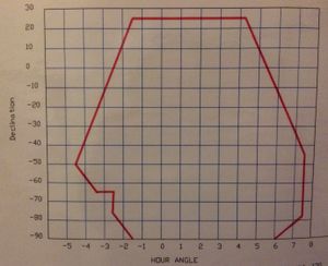
Please note that SpUpNIC extends far enough from the bottom of the telescope that the instrument could potentially collide with the north pier when pointing east between declinations of -60 and -80. The situation is aggravated by the fact that the telescope can only be used on the east side of the pier. The result is quite severe pointing restrictions in the east, unfortunately for a declination range that includes the Magellanic Clouds! One is able to auto-slew into that dec range up to an hour angle of -2, and extremely careful manual pointing done from the console on the telescope floor can gain an additional half an hour. The absolute pointing limits are thus -2.5 hours for declinations between -65 and -75.
When pointing automatically from the control room, please take note of where the cyan star appears on the TCS crash-limits plot when you start the slew. If the telescope would need to move through that problem region, abort the auto-slew and rather point manually, using the console on the dome floor.
SpUpNIC Call list
SpUpNIC Instrument software: Carel van Gend - 076 818 1312
Rear-slit-viewer camera & images: Steve Potter - 072 246 7368
Commissioning/general issues: Lisa Crause - 082 498 4780
Telescope software issues: standby **113 (021 201 5178) or 9118
Electronics Issues: standby **103 (021 201 5179 ) or 9117
Mechanical Issues: standby **104 (021 201 5180 )
Introduction
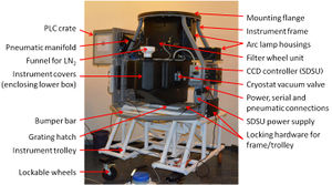
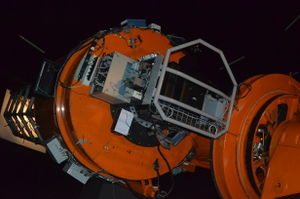
This is the current user manual for SpUpNIC (Spectrograph Upgrade - Newly Improved Cassegrain), the recently upgraded spectrograph at the 1.9-m telescope's Cassegrain focus. See the SpUpNIC paper presented at the 2016 SPIE Astronomical Telescopes and Instrumentation conference in Edinburgh for more information about the instrument, and please cite the SpUpNIC refereed science paper published in the SPIE Journal of Astronomical Telescopes, Instruments and Systems.The spectrograph's collimator and camera optics have been replaced, the instrument has a new detector, all of the mechanisms are now under PLC control and the software (both for instrument control + quick-look data reduction) has been completely re-written. There is also a rear-of-slit camera that makes it easier to acquire targets and focus the telescope properly.
The instrument has two sub-systems, the PLC sub-system (controlling everything that moves) and the detector sub-system (controlling the data acquisition process). The drivers for these sub-systems run as stand-alone processes, and the user interface runs as a separate process on top of these. Typically, users will connect to the graphical user interface (GUI), although certain diagnostic functions may be accessed using the command line interfaces.
We hope that you enjoy using SpUpNIC and that you will provide the instrument team with feedback and suggestions by emailing lisa_at_saao.ac.za.
Change Log
- 27 September 2017: SpUpNIC back in service after fixing a bad connection within the pre-amp electronics. On 8 September the detector began producing only zeros and after extensive trouble-shooting, the detector package was removed from the instrument (on 13 September) and sent down to Cape Town for further investigation and subsequent repair. A total of 12 scheduled nights were lost to this extremely serious failure (although the two observers affected worked with SHOC instead).
- 3 August 2017: Completed extensive testing of various gratings (particularly G7) in order to characterise the ghosting issues reported previously.
- 29 July 2017: Moved the SpUpNIC utility panel to improve the routing of the cables and air hose for the pneumatics to reduce the pointing restrictions in the south east. New software limits will soon be implemented to take advantage of the increased clearance between the spectrograph and the north pier.
- 10 April 2017: G7 replaced with an almost identical new one that does not have fingerprints or scratches! The blaze of the new one is at 5000A, rather than 4600A, since the latter is no longer available from the manufacturer. The 5000A blaze is also a better match for the peak response of this CCD.
- 30 March 2017: New functionality added to the GUI for the rear-of-slit (Lodestar) camera to allow background subtraction. There is now also a slider bar to adjust the brightness of the display, this works best with background subtraction applied.
- 20-25 January 2017: Engineering run during which the cryostat was re-aligned to the rest of the instrument in an attempt to remove what was thought to be coma in the images. Eventually concluded that the faint tails extending redward of arc lines are an optical ghost - a series of reflections thought to arise as light bounces between the CCD and the field-flattener lens that forms the cryostat window. There is no simple fix for this so the effect will just have to be quantified.
- 21 December 2016: Initial documentation for Quick-Look GUI added: https://topswiki.saao.ac.za/index.php/Quick_Look_Tool
- 6-13 December 2016: Another intensive week of software refinement! Highlights include the introduction of: the ability to send target coordinates from the SpUpNIC target catalogue file to the TCS (both for pointing and for downloading finder charts), a new exposure tab for automatically running sequences of exposures (e.g. arc-object-arc procedures), a more streamlined Hartmann routine, as well as the general tidying up of various minor software issues. Also the start of comprehensive documentation of the SpUpNIC Control and Quick-Look GUIs.
- 9 November 2016: Installed a new grating lock that restores full software control of the grating mechanism, while maintaining stability of the grating angle. The user can now change gratings and optimise the wavelength range by changing the grating angle via the SpUpNIC Control GUI (without having to call for technical support).
- 5 August 2016: The cryostat lost vacuum and warmed up. We're not sure what caused this, but suspect that the cryostat valve had not been closed tightly enough and so the vacuum gradually degraded. Leak-testing revealed nothing so we pumped the cryostat over night and the observers were back on-sky a night later.
- 30 July 2016: A new version of the Quick-Look GUI has been installed and seems to be working reliably, please report any issues to Lisa Crause (lisa_at_saao.ac.za) and David Gilbank (gilbank_at_saao.ac.za).
- 28 July 2016: The SpUpNIC optics fogged up due to a massive condensation event in the 1.9-m dome. A temporary dry nitrogen purge was introduced into the instrument to drive out the moisture - fortunately no real harm was done.
- 1 June 2016: Disabled the input field and Go button for changing the grating angle in the instrument control GUI (to accompany the hardware changes described below). Please contact the standby electronics technician if you wish to change either the grating angle or the grating.
- 26 May 2016: A mechanical brake was installed on the grating mechanism to eliminate play in the system (this will be replaced with an electro-mechanical solution to be developed over the coming months).
- 25 May 2016: The inner surfaces of the instrument covers were coated with resin to stop the generation of fine fibre-glass dust.
- 5 May 2016: The optics in the lower box were cleaned to get rid of the fine dust that was being liberated by the instrument covers.
- 16-23 December 2015: The SpUpNIC software evolved substantially during this week. The wiki has been adapted to reflect these and other subsequent changes.
Quick Start
This is a basic overview of taking data; if you're unsure about anything, the Advanced User Guide section contains more information.
- If the instrument Control and Quick-Look interfaces are not running, they may be started from the panel on the left edge of the left screen. The SpUpNIC Control GUI is started with the absorption spectrum icon
 , and the Quick-Look GUI from the emission spectrum icon
  .
. - Ensure that the grating you require is inserted (see the grating change instructions in the Start of Run Section), and then set the grating to the required angle.
- Check that the required filter is in the beam (or left open if required).
- Run a Hartmann routine (see the Advanced User Guide) to establish the best focus for the spectrograph.
- Set the required spectrograph camera focus.
- Set the slit width.
- Select the exposure type (ARC, BIAS, SCIENCE, FLAT, TEST).
- If appropriate, set the exposure time and number of exposures.
- Load your target catalogue file.
- Select a target from the target catalogue file so that the object name and coordinates will go into the fits header.
- If taking a science image, acquire the target, and ensure that it is visible through the slit and in focus.
- If taking an arc, ensure that the arc mirror is in-beam, and the required arc lamp is on.
- Select the SCIENCE exposure type after taking an arc, this will turn off the arc lamp and remove the arc mirror.
- Start the exposure with the Expose button.
- The countdown timer will show the time remaining, and the progress bar will first show the exposure completion state, and then the readout state.
- The software remembers settings used previously for given exposure types (e.g. 3 x 600 sec for a SCIENCE observation, or 25 x 30 sec for FLAT) so keep an eye out for this before you hit Expose for a new setup.
SpUpNIC User Interfaces
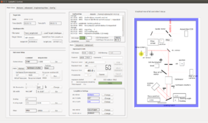
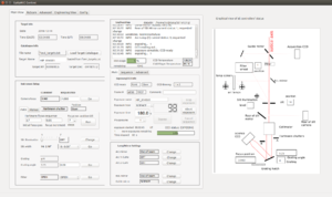
SpUpNIC's displays are labelled "Monitor 1" and "Monitor 2", and are located to the right of the TCS monitor in the warm room. To launch the SpUpNIC Control GUI, click on the absorption spectrum icon in the menu bar on the left-hand-side of Monitor 1. All of the spectrograph sub-systems (e.g. grating angle, slit width, arcs, exposures, guide mirror) are controlled from this GUI.
There's an accompanying SpUpNIC Quick-Look GUI https://topswiki.saao.ac.za/index.php/Quick_Look_Tool , which displays each spectrum after readout and allows basic extraction and wavelength calibration. To launch the SpUpNIC Quick-Look, click on the emission line icon below the absorption spectrum icon on the left-hand edge of Monitor 1.
The Instrument Schematic
Normal operations are performed in the Main View tab of the SpUpNIC Control interface. On the right-hand-side is a graphical representation of the instrument, which shows the light path through the various components controlled by the GUI. You can click on the guide mirror, arc mirror, rear-of-slit mirror and Hartmann shutters to move them in and out of the beam, and on the arc lamps and slit illumination to switch them on and off. A blue border surrounding the graphic indicates that the spectrograph is configured for acquisition or calibration, i.e. some component is in the beam that would obstruct its path to the science detector. If the system is correctly set up for a science exposure, there will be no coloured frame and the red light-path will reach the detector.Detailed Users Guide
- The SpUpNIC Control interface has a number of tabs:
- The Main View tab, in which you'll spend most of your time.
- The RoScam tab, which will later include the rear-of-slit GUI.
- The Advanced tab, used at the start of the run, and which may be used if things go wrong (e.g. to reset or initialise mechanisms).
- The Engineering View tab, which displays various diagnostic settings and allows one to check the CCD and cold finger temperatures.
- The Config tab, which you should not need for the most part, although this is where the temporary software lock for the grating is now.
- The panel on the right is an interactive schematic representation of the instrument. Components with in/out or on/off states can be toggled by clicking on the relevant part of the image. The light path is shown in red so that one can easily verify the instrument configuration.
Start Of Run
Setting name and run number
In the SpUpNIC Control GUI:
- At the start of your run, click on the Advanced tab. In the Observer Info box, enter your name and increment the run number by +1 from the number that was in there for the previous user. In the past, one would determine the run number by looking in the old triplicate observing log book. But the Quick-Look GUI now keeps a detailed electronic log based on fits header info, so users are moving away from keeping a handwritten log. The last logbook entry thus may not give the appropriate run number.
Setting up the grating
- SpUpNIC suffered severe grating instability problems that were incrementally reduced through various interventions, the last of which was the introduction (in early November 2016) of a pneumatically-actuated lock to clamp the grating mechanism at the user-defined angle. The lock is under software control and can thus be de-activated by the user in order to adjust the grating. We are delighted to report that the lock has eliminated the last of the play within the grating mechanism! Flexure remains inevitable for a Cassegrain spectrgraph as it swings about the sky on the back of the telescope. Therefore we still recommend that users bracket their target observations with arcs (taken immediately before and after the object exposures) so as to calibrate out any remaining shifts due to flexure.
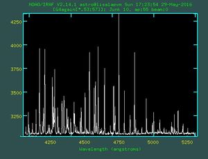
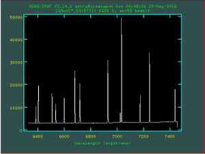
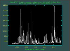
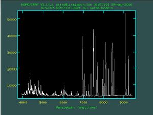
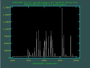
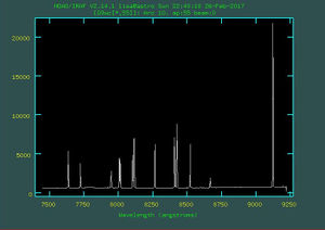
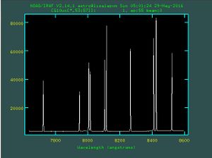
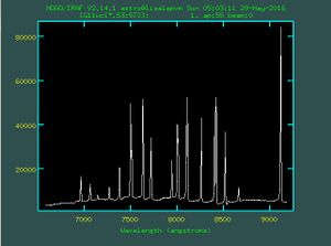
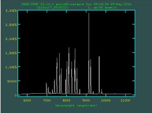
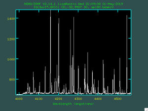
- The angles listed in the second last column of the table below will get one into the range where lines are visible for a given grating, then adjust the grating angle (decrease/increase the angle to go more red/blue) to obtain the desired wavelength range - consult the sample arcs in the right-hand column of the table and the arc maps linked to below.
- Click on the following links for Arc Maps for G4, G5, G6 and G7. Otherwise, here are additional sets of maps for CuNe (for G5) and CuAr (for all the other gratings) with many more lines identified.
- Click on the following link for Sample Spectra of Spectrophotometric Standard Stars observed with G4, G5, G6 and G7.
| Grating | Lines/mm | Blaze (A) | 2-Pix (A) | Range (A) | Star Filter | Arc Lamp | Arc Filter | ~ Angle | Arc Map |
|---|---|---|---|---|---|---|---|---|---|
| 4 | 1200 | 5100 | 1.3 | 1250 | None | CuAr | None | 3 | |
| 5 | 1200 | 6200 | 1.1 | 1130 | GG495 | CuNe | GG495 | -4 | |
| 6 | 600 | 5100 | 2.7 | 2780 | None | CuAr | None | 13 | |
| 7 | 300 | 5000 | 5.4 | 5550 | None | CuAr | BG38 | 16 | |
| 8 | 400 | 8500 | 4.4 | 4130 | GG495 | CuAr | GG495 | 12 | |
| 9 | 830 | 7800 | 1.7 | 1750 | GG495 | CuAr | GG495 | 0 | |
| 10 | 1200 | 10000 | 0.95 | 960 | GG495 | CuAr | GG495 | -9 | |
| 11 | 600 | 10000 | 2.5 | 2600 | GG495 | CuAr | GG495 | 7 | |
| 12 | 300 | 10000 | 5.5 | 5630 | GG495 | CuAr | GG495 | 14 | |
| 13 | 2160 | 5000 | 0.54 | 580 | None | CuAr | None | -8 |
- If a grating is mounted in the spectrograph, it will be indicated at the bottom of the Instrument Setup pane, e.g. gr8 in the Grating field shows that Grating 8 is installed. Above that is the Grating angle field.
- If you need to change to a different grating, follow the steps below - being EXTREMELY careful not to touch, or even breathe on, the optical surface!
 GRATING CHANGE INSTRUCTIONS:
 - set the grating angle to 0 deg in the SpUpNIC control GUI
 - set the telescope vertical
 - position the ladder on the north side (so that you ascend from the south)
 - undo the two quarter-turn fasteners on the grating hatch
 - hold the grating handle at all times while undoing the 3 orange knobs that secure the grating
 - the bolts are captive so they will unscrew and slide back, but not fall out
 - carefully retract the grating, keeping it level as you do so (you may need to wriggle it slightly if it seems tight)
 - take the grating that was in the instrument to the grating room on the NW side of the dome and replace it in its box
 - select the desired grating from its box and take it out to the telescope
 - at the telescope, ensure the grating's orientated correctly (2 bolts on 1 side, 1 on the other) before trying to insert it
 - keep the grating level to insert it, applying firm upward pressure until it's flush with the edges of the grating holder frame
 - keep hold of the handle and apply gentle upward pressure while you tighten the bolts
 - if any of the bolts feel stiff or awkward during tightening, gently wiggle the grating a bit (the bolts should turn easily)
 - continue tightening until all 3 bolts are fully secure (and can turn no further)
 - with all 3 bolts screwed in fully, close the hatch and lock the quarter-turn fasteners
 - remove the ladder
 - go to the Advanced tab on the control GUI and click the grating angle initialise button (in the bank of buttons on the left)
- Once you have the correct grating in the spectrograph, enter an approximate starting angle (see the grating table above) in the Grating angle box and click Go.
- Take an arc and check the wavelength range on the Quick-Look extraction that will appear shortly after the image is read out.
- If the spectrum is too blue (red), decrease (increase) the grating angle and repeat the arc to check the new wavelength range - iterate until happy with the range.
- Note that angle changes <0.05 degrees are too small, so make a larger change and then go back the other way to achieve very small shifts (the software takes care of backlash in the system by ensuring that the desired value is always approached from the appropriate direction).
- The software knows which order-blocking filters should be used with each grating, but it is still a good idea to check that the correct filter is selected (refer to the table above). If necessary, select the required filter from the drop-down menu at the bottom of the Instrument Setup pane and click Go.
Arc lamp and filter selection
- Two arc lamps are permanently mounted in the spectrograph - you no longer need to swap out a lamp - but the arc lamp filters are still changed manually. On the spectrograph, the CuNe lamp (Lamp 1) is in the horizontal housing, with two slots for filters in the light path. The vertically housed CuAr lamp (Lamp 2) is above it, similarly with slots for two filters at the bottom. Filter requirements are listed in the table above and the filters are stored in a small, labelled wooden box on the bench in the grating room (on the NW side of the dome).
- The software now decides, based on which grating is in use, which lamp to switch on once ARC is selected from the Exposure type drop-down list on the Exposure/CCD info pane.
- Alternatively, click on the appropriate lamp icon in the instrument schematic - this will switch on the lamp and insert the arc mirror into the beam. Having taken the arc, simply click on the arc mirror icon in the schematic to remove the arc mirror and switch the lamp off. One can also control the lamps using the Lamp/Mirror Settings pane of the SpUpNIC Control GUI. Click the appropriate Change state button to switch the desired lamp on/off, and to move the arc mirror into the beam to take an arc exposure.
Daily Daytime Tasks
Bias Frames
The spectrograph camera does not have a shutter, so even though bias frames are zero second exposures, you still need to take them when no light can reach the detector. Ideally while the mirror cover is still closed, or at least not while pointing to an object, or while an arc lamp or the slit illumination etc is on. The bias level on SpUpNIC is stable, but these frames take next-to-no time, so just snap a bunch of them (say 25?) every day.
Dome Flats
Dome flats give a measure of the pixel-to-pixel sensitivity variations over the CCD. The dome's white flat-field screen is not perfectly evenly illuminated by the lamps on the top end of the telescope, but the light goes through the slit, gets collimated, diffracted and re-focussed, so that is not a problem. We do not use the sky for this as you would get spectra of the Sun!
- Behind the control room desk, dial the rheostat fully anti-clockwise to zero- Flip the switch in front of it to On - Dial the rheostat up to 140 V - do not exceed that value as you will blow the lamps - this value has decreased from 220 V since new lamps were installed in July 2019 - The lamps on the top end of the telescope should now be on - Open the mirror cover - With the telescope vertical, rotate the dome to 127 degrees, so that the white flat-field screen is just to the east of the south pier - Set the telescope RA to HA = 0 - Slew the telescope in Dec to the south pole (-90 degrees), while keeping an eye on the spectrograph cables - The cables will look like snagging, but they will not if you are at HA ~ 0 - Slew Through the pole, to -86.5 degrees (on the other side of -90) - Try not to overshoot as the pointing limit is at -85 on that side - If you run into the limit, an alarm will sound and the telescope will stop moving - To recover: turn the over-ride key next to the console while backing the telescope out towards the north in Dec - With the telescope at HA ~ 0/12 & Dec ~ -86:30, the telescope should be quite well centred on the flat-field screen - In the control room, take some trial exposures to check the count level, aim for ~40k counts - The lamps are quite red, so blue settings (e.g. G4) struggle for counts - In that case, it is fine to crank the slit wide open to let more light in (you do not care about resolution here) - Take as many flats as you like (say, 11?) once you have established an appropriate exposure time - When you have the flats, slew the telescope back to the zenith (again keeping an eye on the cables) - Dial the rheostat down to zero - Flip the switch to Off - Close the mirror cover
Focusing The Spectrograph - running a Hartmann sequence
Before each night's observations, you should focus the spectrograph. This is done using a scripted Hartmann sequence run from the SpUpNIC Control GUI. The process moves a shutter halfway into the beam, takes an arc exposure; then blocks the other half of the beam and takes a second arc exposure. The arc lines are then cross-correlated to measure the shift between the two. The procedure is repeated at a range of camera focus positions until the line shifts are minimised, indicating best focus. This procedure may be performed manually, but it is typically run automatically, as follows:
- Take an arc to check that the grating angle is correct and to get an idea of the required exposure time (aim for at about 1000 counts in the weaker lines): in the Exposure/CCD info pane on the Main View tab, select "Exposure type" = ARC from the drop-down menu, and enter e.g. 10 seconds in the "Exposure time" box.
- If satisfied with the arc obtained, locate the Hartmann focus sequence panel in the Instrument Setup pane on the Main View tab of the SpUpNIC Control GUI (if not, adapt the exposure time and grating angle as required before proceeding).
- Select the Auto tab and enter the parameters for the Hartmann sequence: 3.6 for the initial focus position, 0.05 for the focus increment and 9 for the number of steps - with the system still set up as it was for the test arc (lamp on, arc mirror in beam), click Run.
- The slit width will automatically be set to 1.05" and the exposure type will switch to HARTMANN, then the GUI will grey out and not be available during the focus sequence (although you will see the Current Camera Focus field changing and the Hartmann shutters indicate Moving.
- On completion of the sequence: in the SpUpNIC Quick-Look GUI, in the log box to the right of the spectrum display window, you will see a list of focus positions and their corresponding pixel shifts. Best focus corresponds to a shift of zero.
- Enter the best focus into the Requested Camera Focus box on the SpUpNIC Control GUI's Instrument Setup pane and click Go.
- The Hartmann sequence ends with the shutter out of the beam, but for some reason it sends the slit width to zero! So select the desired slit width in the Instrument Setup pane and click Go. Check that it goes to the required position, click Go again if it does not do it the first time.
- Select "Exposure type" = ARC and take an arc to confirm that the focus looks good.
- Click on the arc mirror in the schematic to switch off the arc lamp and move the arc mirror out of the beam.
Observing Setup
Target Catalogue File
Target names and coordinates get propagated into the fits headers by loading a target catalogue file into the Target Info pane and then selecting the appropriate target.
- Open a terminal on the SpUpNIC PC and use your favourite text editor to produce a simple text file (e.g. Run007.txt) with the format shown below:
 Target_1_name HH:MM:SS -DD:MM:SS J2000
 Target_2_name HH:MM:SS -DD:MM:SS J2000
 Target_3_name HH:MM:SS -DD:MM:SS J2000
(Note: do not include spaces in the target names and use single spaces between the object name, RA, Dec and Equinox)
- Click on the Load Target Catalogue button, then navigate to, and select, your catalogue.
- Select the appropriate target name from the drop-down list that appears after the catalogue file has been loaded.
- If you edit the catalogue file, you'll need to reload it into the GUI before the changes will appear in the drop-down list.
Setting up the slit position on the TCS - using the SpUpNIC Control GUI
The purpose of this step is to figure out where on the acquisition image you need to place your star, in order for it to land close to the ideal spot on the slit. Very bright stars can be seen reflected on the slit jaws, and can be placed on the slit directly, but this is not the case for fainter stars, which need the superior reflectivity of the guide mirror in order to be seen on the acquisition camera. This position should be stable throughout your run, but it is worth checking every couple of days that the red box on the acquisition camera screen still corresponds to the appropriate position on the slit. This is much easier now that the instrument has a rear-of-slit camera!
- Move the guide mirror into the beam, either by setting the Acquisition state in the Lamp/Mirror Settings pane of the SpUpNIC control GUI (if it says Guide Mirror Science, click Change), or by clicking on the guide mirror in the instrument schematic.
- Acquire a bright star (e.g. ~4th mag from the Bright Stars chapter of the Sutherland Almanac, available in the warm room), roughly centre it in the acquisition camera field and continue exposing.
- Move the guide mirror out of the beam (i.e. centre the mirror so that light can go down the central hole).
- Move the rear-of-slit mirror into the beam (Lamp/Mirror Settings pane, RoS mirror change from Out of beam to In beam).
- Turn on the slit illumination (in the Instrument Setup pane, Change to turn on the lamp). Tune the exposure time/LUT sliders on the TCS until you can clearly see the slit running horizontally across the acquisition image, approximately halfway up.
- Using the hand paddle, move the telescope to place the star on the slit, approximately one quarter of the image width away from the right-hand edge.
- Turn off slit illumination.
- Click on the icon
 for the rear of slit camera (on the left-hand side of Monitor 1).
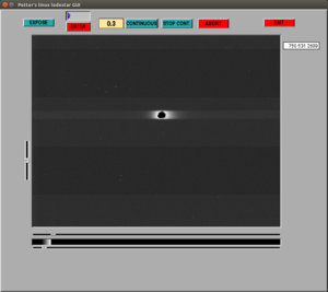
 - An image window for the rear-of-slit camera will pop up. This looks up at the slit from below, to enable you to check that your star is centred on the slit. Move the telescope such that the star falls on the centre of the slit image in both x and y.
- Move the rear-of-slit mirror out of the beam and take a test spectrum (e.g. 20 seconds) of the bright star (in the Exposure/CCD info pane, select Exposure type = SCIENCE from the drop-down menu, enter 20 in Exposure time and click Expose).
- The resulting image will be displayed on the Quick-Look GUI, on Monitor 2. You are aiming for the spectrum to fall on approximately the central row of pixels within the image area (note that this is a roughly central band that only covers about half the vertical extent of the CCD). If the spectrum is too high or low, move the telescope slightly in RA (the RA- button moves the spectrum downwards in the image), iterate until the star is well positioned.
- Once you are happy with the position of the spectrum on the image, go back to the TCS and add a red marker over the position of the star on the slit (TCS Pointer pane: Markers, Add a red marker).
- Finally, move the guide mirror into the beam, and add a second red marker at the position of the star. This marker will be used to approximately position stars on the slit that are too faint to be seen reflected off the slit jaws.
- The red markers are lost if the TCS software gets restarted, so it is a good idea to note down their coordinates!
Focusing the telescope
- Acquire a ~11th mag star (e.g. one of the spectrophotometric standards) with the guide mirror in the beam
- Position the star on the appropriate red box on the acquisition image
- On the instrument schematic, set the guide mirror to Science (so that light reaches the slit)
- Also insert the rear-of-slit mirror into the beam to direct the light to the Lodestar (rear-of-slit) camera
- View the stand-alone rear-of-slit software window
- Click on the "continuous" button for an ongoing series of 2 second exposures
- Open the slit wide, to about 4"
- Adjust the slider bars at the bottom of the image (both most of the way to the left) to set the brightness and contrast
- Use the hand-paddle to position the star near the centre of the slit (in both X and Y)
- Adjust the telescope focus with the hand-paddle in steps of 3-5 units and assess how the star image changes
- The star will move around due to the translation of the secondary mirror, so adjust it back into view with the hand-paddle if necessary
- Astigmatism in the system extends the star image diagonally and the orientation indicates whether the focus is too high or too low:
 Star extended from upper-left to lower-right: focus number is too high
 Star extended from lower-left to upper-right: focus number is too low
- Best focus is where the star is as round and sharp as possible
- Optimum focus varies with temperature, typical summer values are ~2200 while cold winter nights may be closer to 2270 units
Focusing the acquisition camera
- Having focused the telescope as described above, one needs to focus the acquisition camera.
- The star used to focus the telescope may be too bright, so aim for something fainter (e.g. a guide star that needs a ~1 sec exposure).
- Adjust the acquisition camera focus with the up/down buttons in the lower right corner of the TCS GUI to get the stars as sharp as possible.
User's Troubleshooting Guide
Please be sure to inform the instrument team of any technical issues you encounter during your run, either by emailing lisa(at)saao.ac.za, or by means of the SAAO's online fault forum at [[1]].
Re-starting the Quick-Look software
- There is a memory leak in the Quick-Look software which causes its memory consumption to grow larger each time a new spectrum is loaded. To work around this, please restart the quick-look software once daily, or more often if required. Open a terminal and issue the command
ps aux | grep ql-spupnic
- If nothing is returned, then the quick-look software is not running. If one or more lines are returned, then they describe running instances of the quick-look software.
- Each running process should be terminated before a new instance of the Quick-Look software is started.
- The second column in each line of the output obtained above is a number. This is the process ID (PID) of the running instance. To terminate a running process, issue the command
kill -9 <PID>
where <PID> is the process ID of the process.
- Once all the quick-look processes have been terminated, start a new instance of quick-look by clicking on the Quick-Look icon on the left-hand task bar.
If the Quick Look does not extract spectra for science frames
- A dialogue box saying "Please Wait" lingers just below the image display and no extracted spectrum appears in the plot below
- Dismiss the dialogue box (and any others piled up behind it) until they are all gone
- Locate the Auto and Manual extraction options just below the spatial profile plot in the upper right of the Quick Look main tab
- Click on whichever one is not currently selected (return to the one you want if it's the one that was originally selected)
- Test by loading a science image by selecting one from the Observing Log tab on the Quick Look
- If the problem persists, again make sure the dialogue box(es) are dismissed before stopping and restarting the Quick Look GUI
The Exposure/CCD Info pane gets a red frame and complains about timing issues
- Go to the Advanced tab on that pane
- Click the Reset Exposure Controls button
- If that does not clear the red frame, close the Control GUI
- Open a terminal and type restart_services
- You may be asked for a password, it's the usual one!
- Restart the SpUpNIC Control GUI by clicking on the absorption spectrum quick-launch button
If the slit runs anything but horizontally across the rear-of-slit image, the camera needs mechanical relocation
- The rear-of-slit camera has a spring-loaded kinematic mount which can move slightly if the USB cable snags or the camera gets bumped somehow
- If this happens, the slit image will be displaced, making acquisition difficult
- Insert the rear-of-slit mirror and turn on the slit-illumination to confirm that this is indeed the case
- Go out and grip the rear-of-slit camera assembly (which projects from the south side of the instrument cover) and gently jiggle it - the camera will pop back into its required position
- Use the slit illumination to verify that the slit runs horizontally across the image again
If the rear-of-slit (ROSCam) camera window does not produce any images (though the exposures seem to count down), it probably needs a reset
- Check that you've got the light path right: guide mirror centred and the rear-of-slit mirror in the beam
- Then check that it's not an image scaling issue, by turning on the slit illumination (which is bright enough to show up under most circumstances)
- If you still don't see anything:
-stop ROSCam exposures
-exit the ROSCam GUI
-press the "power cycle ROS camera" button from the TCS GUI
-wait 30s
-restart the ROSCam GUI.
-restart exposures
