SHOC
Contents
- 1 SHOC User Manual
- 1.1 SHOC Call Out list
- 1.2 Introduction
- 1.3 Change Log
- 1.4 Quick Start
- 1.5 Filter wheel
- 1.6 GPS
- 1.7 Camera
- 1.8 Acquiring data
- 1.9 Data Transfer
- 1.10 Advanced users guide
- 1.11 In-depth Information
- 1.12 User's troubleshooting guide
- 2 Technician's guide
SHOC User Manual
- Observation planning tools: There is now a SHOC signal-to-noise ratio, exposure time, and limiting magnitude calculator.
- NOTE: THIS PAGE REFERS TO THE LINUX- and WEB-BASED SOFTWARE (AS OF MARCH, 2015). For the original, manufacturer-based software and instrument commissioning details, please refer to the manual at http://shoc.saao.ac.za/Documents/ShocnHelpful.pdf.
- If you have found this webpage already loaded on the browser, please refresh to ensure that it is current!!
SHOC Call Out list
Instrument software issues: Carel van Gend **050 (0768181312)
Telescope software issues: standby **113 (0829034869) or 9118
Electronics Issues: standby **103 (0767895131) or 9117
Mechanical Issues: standby **104 (07678951232)
- Please report any problems on the fault reports page.
Introduction
The SHOC systems consist of a filterwheel unit (with one or two filterwheels), a GPS unit for providing accurate timing triggers, an Andor iXon camera, and a control PC. Currently there are 2 full SHOC systems (shocnawe & shocndisbelief), and 1 development system running a different camera (shocnhorror). As of March 2015, the control software is web-based. Users point their browser to the instrument location, and separate tabs appear to allow control of the camera, GPS, and filter wheel. SHOC can be mounted on the 1.9- and 1-m telescopes. We have tried to make the usage telescope specific, but it is very useful to know which SHOC instrument is mounted on the telescope you are using. Details on instrument operation are below.
The SHOC website may well have more extensive detail about this instrument.
Dr. Marissa Kotze has written some pipeline software which may help with reduction of SHOC data but from August 2020 the SAAO no longer provides support for this pipeline. Users are now encouraged to use TEA-phot developed by Dominic Bowman and Daniel Holdsworth. TEA-phot
IMPORTANT NOTES
- CONSIDER DECREASING DETECTOR TEMPERATURE IF TAKING LONG EXPOSURES Reports in 2016 indicated that the dark current is higher than expected (by a factor of ~ 100; more information to follow). This is most noticeable for long (>=10 minute) exposures. The camera is automatically cooled to -50C. It can be cooled down to -70 C; however, if the ambient temperature is high, the cooler will be stressed and cannot reach minimum temperatures. If you do adjust the temperature to -60, -65 or -70, please listen carefully so that if the temperature alarm triggers (a high-pitched, continuous beep) you can stop cooling and prevent hardware failure. March 2017
- THE NEW SOFTWARE HAS DIFFERENT FILE NAMES AND HEADER KEYWORDS THAN PREVIOUS DATA. If you use this information in your analyses, you will have to update it. The filename format has been standardized to <Instrument>_YYYYMMDD.####.fits, where the instrument is sha (shocnawe), shd (shocndisbelief), or SHH to designate which SHOC box is being used. Please check the header of a new data file or the wiki FITS header keywords (the "new" keywords are directly from the Andor iXon camera under Linux). March 2015
- THE FILE SIZE IS NO LONGER LIMITED TO 2 GB. This means that if you take large data cubes, the file size has no limit (this is because we are no longer on a Window-based, 32-bit, operating system). If you end up with a very large file, data analysis can be difficult. We are working on an efficient method to automatically split files into smaller sizes, but for now users need to be aware that requesting a large number of images in one file could return a very large file size (and if you mistakenly delete your file, you have lost alot of work!). It is recommended that multiple files be manually taken. If you have any questions or problems with the data, feel free to contact carel@ saao.ac.za or amanda@ saao.ac.za. March 2015
Change Log
Most recent changes at the top
- v1.4.4 Release date 5 December 2018
- Bug: Camera user interface works without any filter wheels
- Feature: Display filter wheel names on the user interface
- v1.4.3 Release date 25 July 2018
- Bug: Fixed GPS antenna reference "off" bug by assigning per-telescope locations
- Feature: Added a button to set GPS start time 30 seconds into the future (uses web browser operating system's time so make sure that your time zone is SAST)
- v1.4.2 Release date 3 January 2018
- Feature: Better error reporting
- Feature: TCS info now available when mounted on the 40-inch
- v1.4.0 Release date 23 November 2016
- Bug: Camera interface doesn't revert to "manual mode" when reloading the page while it's in scripting mode
- Feature: Upgraded to JS9 v1.10 (Release Notes)
- Feature: Display and plot total counts for active regions on image display
- v1.3.5 Release date 16 November 2016
- Feature: GPS driver now has access to a general-purpose SHOC config file
- Feature: GPS antenna delay is now set from the config file
- v1.3.4 Release date 19 October 2016
- Bug: Default image display orientation. The image shown on-screen in conventional mode should now be correctly oriented.
- v1.3.3 Release date 17 August 2016
- Bug: EM amplifiers are not selectable
- Bug: 74" GPS antenna reference off (CLI only)
- Bug: Fixed bug where start button says 'Start' instead of 'Stop'
- Feature: GPS static and dynamic mode options (CLI only)
- Feature: Shorter exposure times for kinetic series = 1
- v1.3.2 Release date 4 May 2016
- Bug: Filterwheel sometimes doesn't initialise on the first try.
- Bug: Plot 1 point per exposure on analysis tab.
- Feature: Turn off GPS pulses at restart_services.
- Feature: Configurable audio signal when exposures are complete.
- v1.3.1 Release date 6 April 2016
- Bug: If the output amp is switched, x should be flipped to the opposite of what it was.
- Bug: Ambient temperature keword is now ENVTEM. No longer clobbers CCD temp keyword (TEMP).
- Bug: TCS related keywords were not always correctly updated.
- Bug: The SHOC cameras were referred to by the usual instruments to which they were attached. Now use serial number.
- Bug: Fix to allow ampersand characters in additional header fields.
- Bug: Scripting should now be working as expected.
- Feature: Use logrotate to prevent log files from getting too big
- v.1.3.0 Release date 10 February 2016
- Bug: Camera freezes up, requiring restart_services
- Bug: When acquisition is stopped before first trigger is received, counter is nevertheless incremented.
- Bug: Controller doesn't know about GPS when running in external mode
- Bug: TCS information not appearing in FITS headers
- Bug: Temperature reported as "N/A" when reloading camera interface
- Feature: Swap "move" and "initialize" buttons on filter interface
- Feature: Add additional binning options for scripting
- v1.2.2 Release date: 14 October 2015
- Bug: Subframe parameters will automatically adjust to allowable values based on binning configuration.
- Bug: Fixed JS9 Zscale bug.
- Feature: Basic authentication from within the web interface.
- Feature: Scripts can be repeated by entering a value in the "script iterations" field from the advanced tab.
- v1.2.1 Release date: 15 July 2015
- Bug: Camera properties are looked up in a table, in the controller, so the driver no longer needs to query the camera each time for these.
- Bug: Directories for saved data are now lowercase e.g. sha not SHA (this now follows SAAO standards).
- Feature: Filter wheel ID and slot number are now included in the FITS headers.
- v1.2.0 Release date: 17 June 2015
- Bug: Incorrect counts displayed on analysis page
- Feature: Only display one filter wheel interface when only one wheel is configured
- Feature: Scripting capabilities
- v1.1.3 Release date: 13 May 2015
- Bug: Some of the input fields on the camera form don't get disabled when acquiring data
- v1.1.2 Release date: 4 May 2015
- Bug: Counts in display appear to be negative when they exceed ~30,000
- v1.1.1 Release date: 29 April 2015
- The following changes have been affected:
- Data is copied from the spool directory to the final directory _before_ the supplementary FITS header keywords are added.
- The following changes have been affected:
- v1.1 Release date of 1.1: 18 April 2015
- From v1.0 released 25 March 2015, the following changes have been affected
- Images were horizontally flipped and shouldn't be (SHA; 20150325)
- Filter keywords in FITS header are now the colour, not number
- Exposure label on interface now reset when changing from external to internal mode
- Exposure time now set to 0 in external mode
- A header keyword conversion script from the old headers (prior to v1.1) to the new headers (v1.1) to be able to run old data through Marissa's updated pipeline.
- New data entry under the Camera -> Advanced -> Additional Header Keywords for astronomer to enter header keywords related to target/RA/Dec/additional information
- specifically for the 74in telescope, addition of FITS header keywords from the TCS. NOT AVAILABLE IN THE 40in TELESCOPE
- DATE-OBS field contains decimal part twice fixed
- At 16:30 daily, the restart_services will be run from cron
- sudo adjusted to be able to run all services needed including restart_services, rescue_data.py and ....??????
- From v1.0 released 25 March 2015, the following changes have been affected
Quick Start
- Connect to the web browser. Go to http://shoc40in.suth.saao.ac.za:5000 or http://shoc74in.suth.saao.ac.za:5000 depending on which telescope you are using.
- If you are prompted to log in, use the shoc74in or shoc40in username and password, depending on which telescope you are using (passwords are the same as those used in the data transfer section, and should be obtained during startoff)
- Initialize the filter wheels and select your filter. You must initialize both filter wheels whenever the webservice is started.
- Click on camera tab: turn on the camera and confirm that it is cooling.
- If using the GPS to trigger data frames, click on GPS tab: check that the GPS has valid time and can be set.
- Click on camera tab: set parameters on the camera and start previewing and taking data.
- Transfer data from the instrument to your local machine or the SAN.
- Make sure to turn OFF GPS trigger pulses when you are done with them.
- Turn OFF the camera before you leave!!
Filter wheel
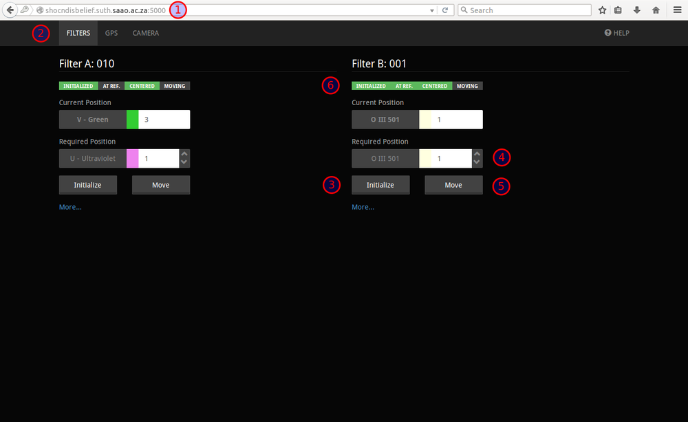
- (1) Point your browser at shoc40in.suth.saao.ac.za:5000 or shoc74in.suth.saao.ac.za:5000
NOTE: ON DNS ALIASES: These telescope web addresses are aliases to the SHOC instruments. The real addresses for the instruments are shocnawe.suth.saao.ac.za:5000 or shocndisbelief.suth.saao.ac.za:5000. In order to avoid confusion, or the requirement that the user know which instrument is mounted on their telescope, we have created the aliases.
- (2)Select the filterwheel tab
- Initialize the filterwheel(s) (3), then select the filter required (4), click "Move" (5). The "Centered" indicator should be green when the wheel is finished moving (6).
GPS
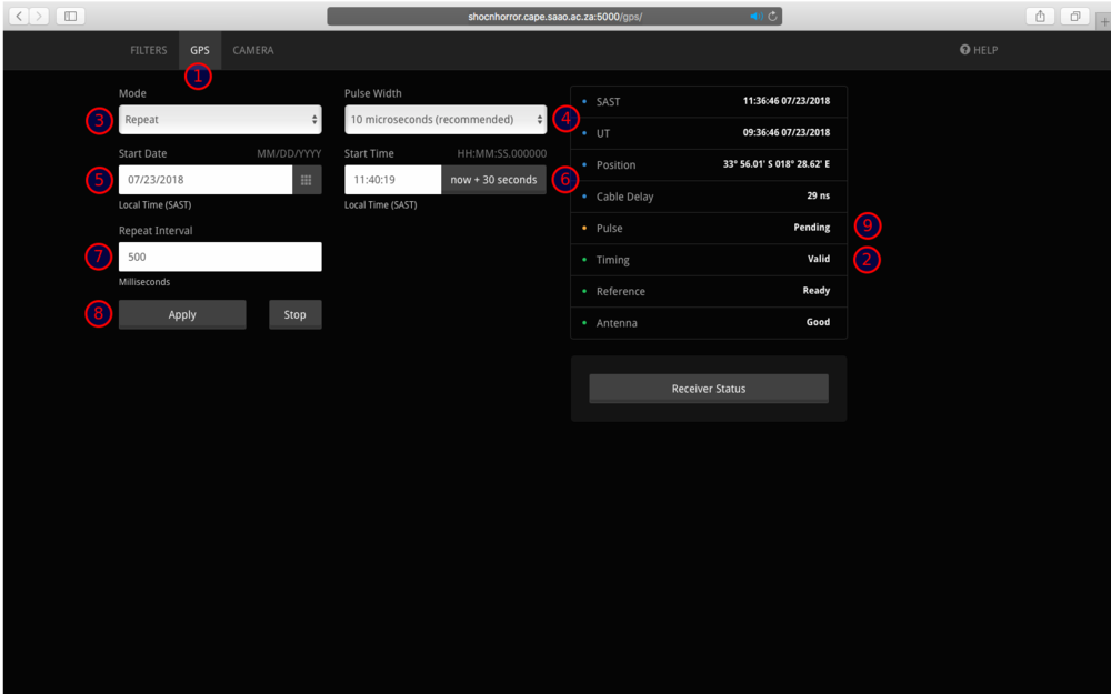
- If using external triggering, select the GPS tab (1)
- Ensure timing is valid (2).
- Set the Programmed Output Pulse (POP) parameters (mode (3), pulse width (4), start date (5), start time (6) (NOTE: the "now + 30 seconds" button uses your browser's time so make sure your operating system is set to local time), trigger interval (7)) and click apply (8). The status should change to pending (9).
- The recommended default pulse width is 10 microseconds.
Camera
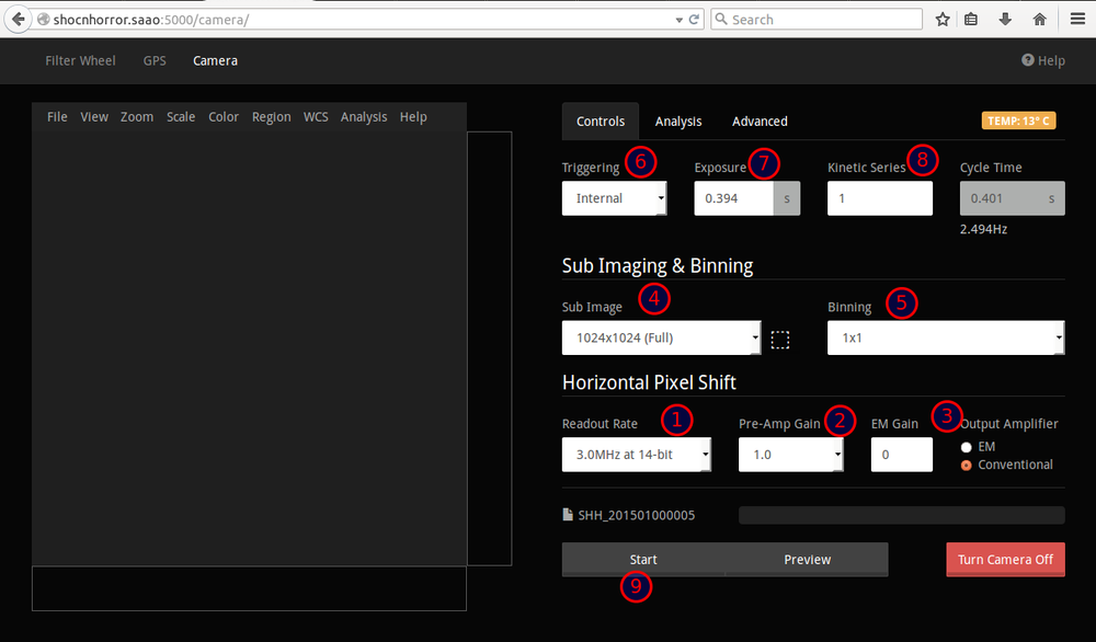
- Select the camera tab (1).
- Turn the camera on (2)
- Set the desired Readout Rate (1), Preamp (2) and Electron Multiplying (3) parameters (NB: EM MODE MAY ONLY BE SET IF YOU HAVE WRITTEN PERMISSION TO DO SO).
- Set the sub image (4) and binning (5) parameters.
- Set the trigger type (6), exposure (7) and kinetic series (8) parameters. Note that an entry of "0" in the Exposure field (7) will default to the minimal possible exposure time.
- Start the acquisition (9).
Acquiring data
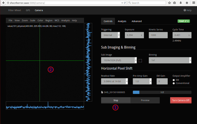
- Stop to abort (1), or wait until completion. The image display area (based on DS9) (2) shows snapshots of the images throughout the acquisition.
- When the series is complete, the FITS data cube is copied to /data/<telescope>/<INSTR>/<YYYY>/<MMDD>/<filename>.fits, where:
- <telescope> is 40in or 74in,
- <INSTR> could be shd for shocndisbelief, sha for shocnawe or shh for shocnhorror,
- <YYYY> is the year,
- <MMDD> is the month and day, (Note that YYYY/MMDD is that of the start of the night and is increased at NOON the following day.)
- <filename> is the instrument abbreviation in uppercase (SHA, SHD or SHH) followed by the date in YYYYMMDD format and the number of the acquisition.
- An example is /data/74in/sha/2015/0325/SHA_20150325.0001.fits
- Make sure to turn off the camera when you are done for the night.
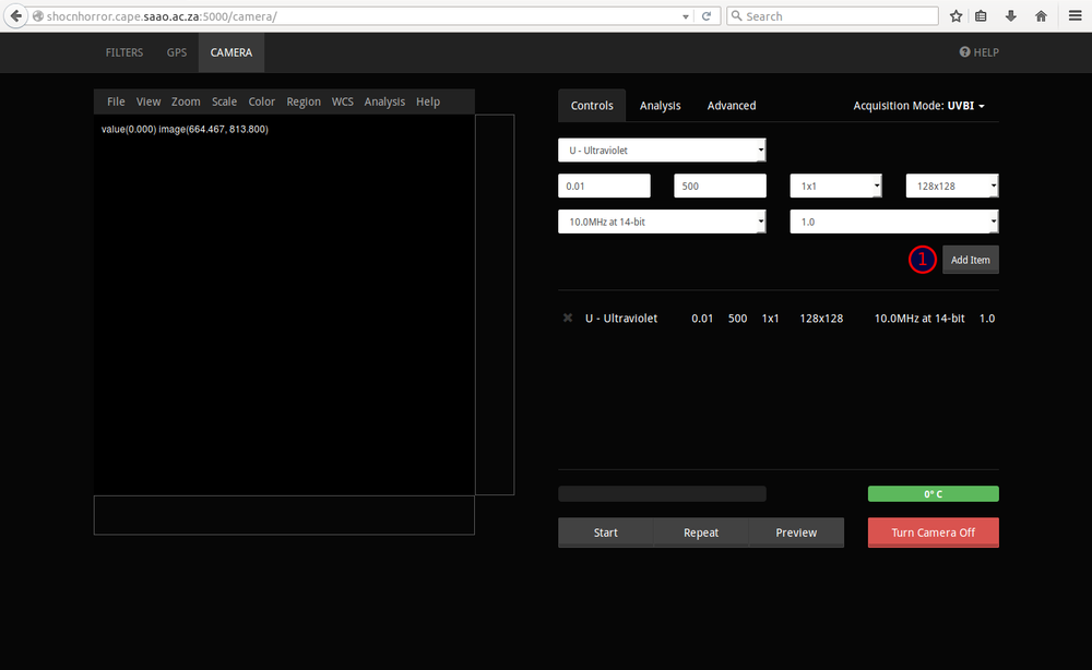
Automated Data Acquisition (Scripting)
When running a series of exposures on the same target with different filters it can be useful to make use of the automated acquisition mode on the camera tab. NOTE: SCRIPTING ALWAYS USES THE INTERNAL TRIGGER
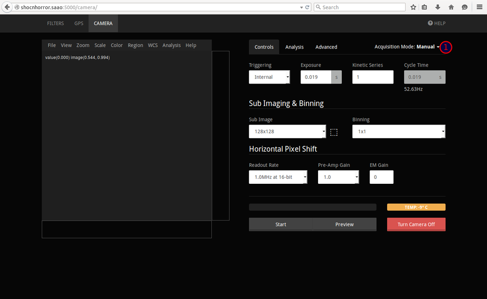
(1) You can switch between the conventional "Manual" acquisition mode and automated mode by clicking on the option menu to the right of the tabs on the camera interface.
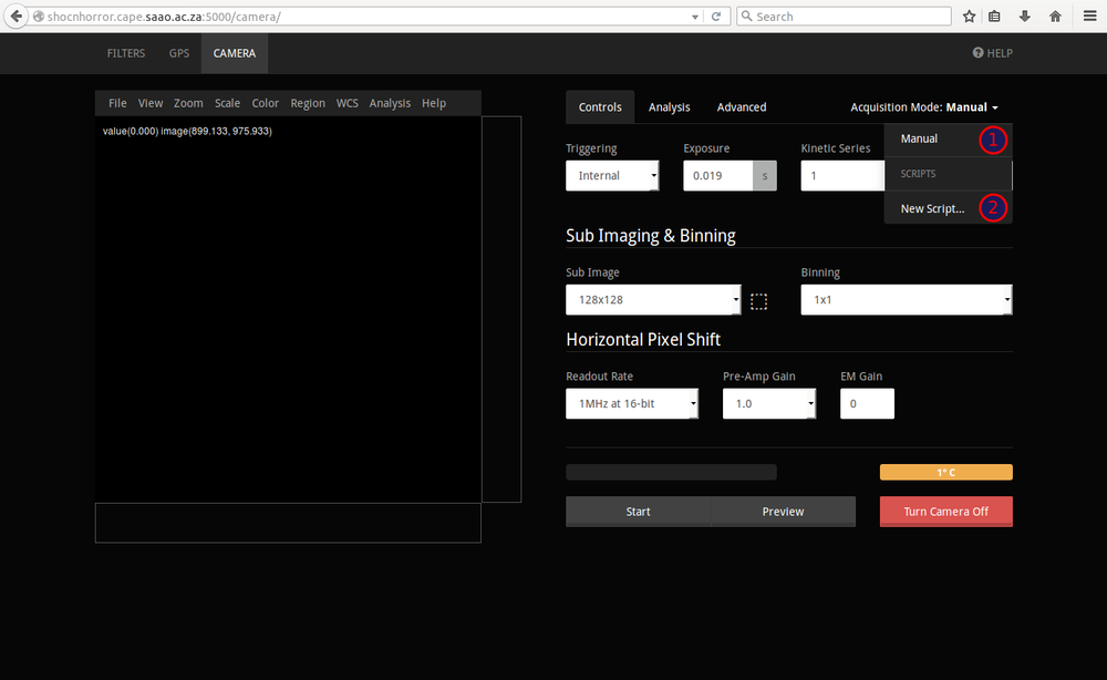
(1) Opening the menu will display a list of existing scripts as well as an (2) option for creating new ones.
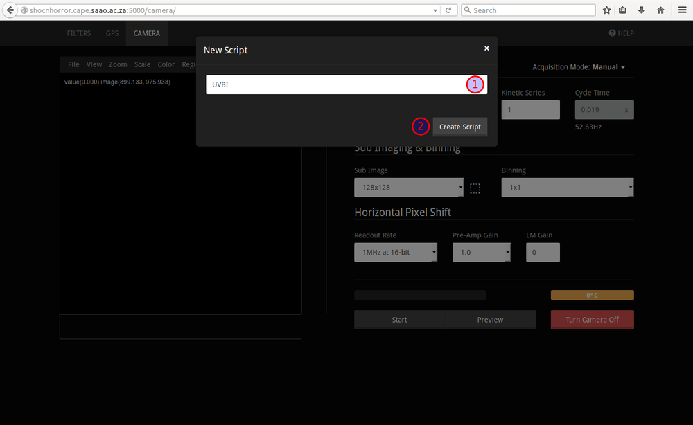
When you click the "New script" option a dialog will appear giving you (1) a text field to enter a name for your new script. You can then enter any name and click the (2) "Create Script" button to create a new one. NOTE: Please ensure that your script has an easily identifiable name for the observer and run, e.g. Sickafoose_20150617Script1. All scripts are currently being stored in the drop-down web interface -- this means you will see other people's scripts and will have to look there for your own in order to load the script in subsequent observing runs.
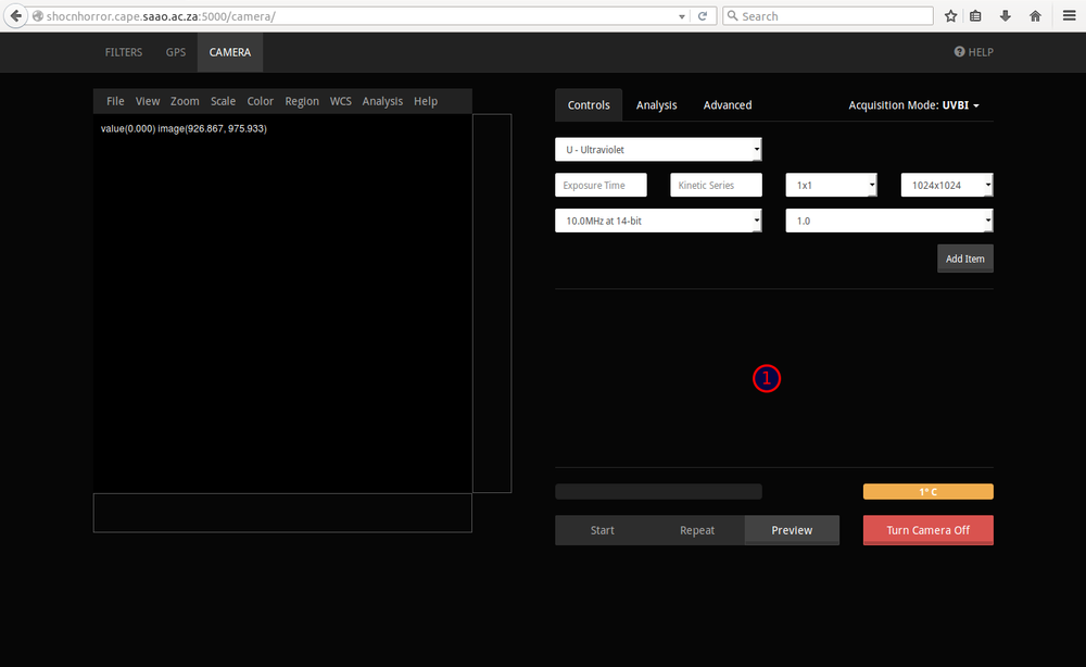
(1) This will then display a new, empty section where you can add a sequence of acquisitions.
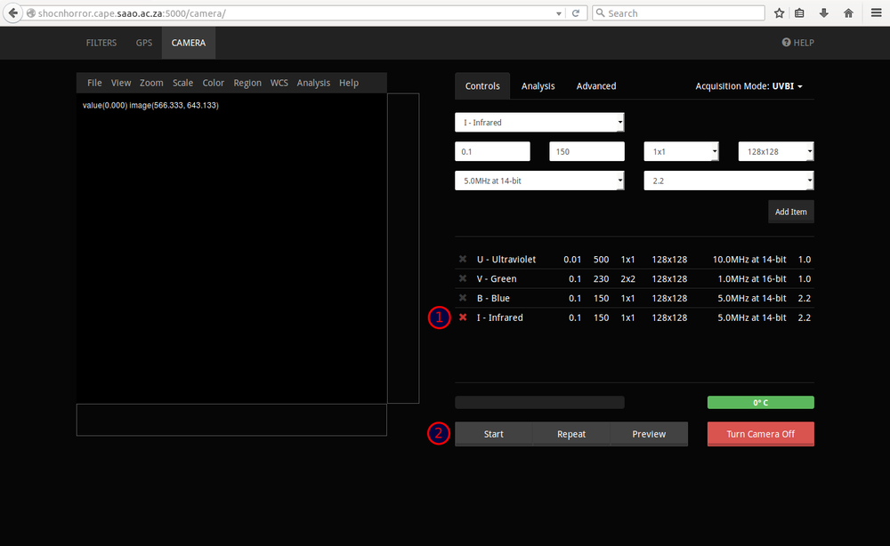
You can add as many line items as required by entering the appropriate values and clicking the (1) "Add Item" button.
If you make any mistakes while adding items, you can remove individual ones by clicking the (1) cross icon next to it. Once you're happy with the sequence, clicking the (2) "Start" button will start your automated acquisition.
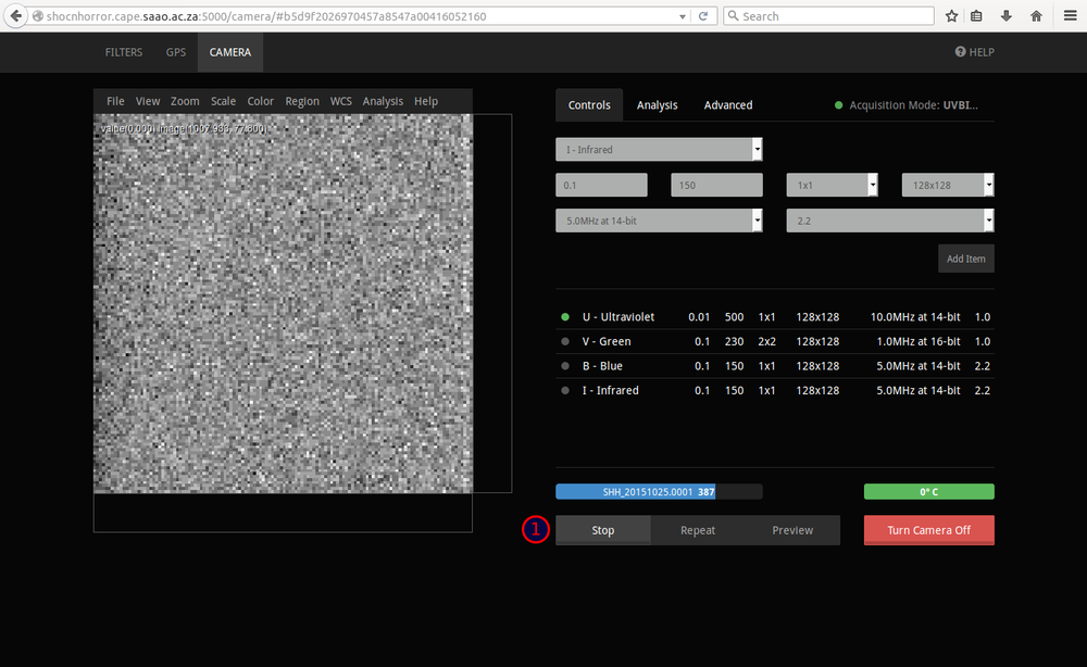
Unless you click the (1) "Stop" button while the acquisition sequence is in progress, the sequence will run to completion.
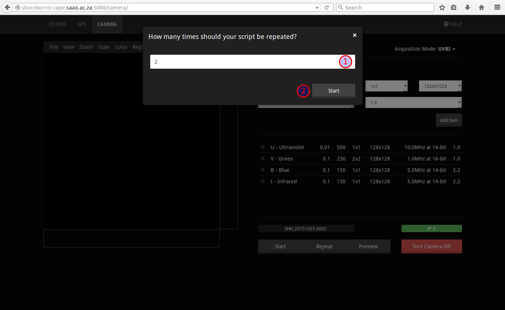
Scripts can also be repeated by clicking the repeat button, entering the number of times the script should be repeated and clicking the (2) "Start" button.
Data Transfer
There is an automatic transfer of data from the instrument to the file servers in Sutherland and Cape Town, every morning at 7:30. So you should not need to worry about the security of your data. However, you'll still need to access your data! We describe here how to do this. There are two ways to get the data: (1) directly from the instrument PC or (2) from the SAAO storage area network (SAN).
To use method (1):
- Open a shell on your local PC (Putty if you're using Windows or a bash/tcsh/sh if on Mac or Linux)
- Copy the data using the following command, depending on the telescope:
       rsync -avzP shoc74in@shoc74in.suth.saao.ac.za:/data/74in/sh?/<YYYY>/<MMDD>/*.fits /LocalFilePath
       rsync -avzP shoc40in@shoc40in.suth.saao.ac.za:/data/40in/sh?/<YYYY>/<MMDD>/*.fits  /LocalFilePath
         ---- where sh? is a wildcard that will point to the correct instrument mounted on the
                telescope for that night and "/LocalFilePath" is the location on your local machine
         ---- the password is that for the shoc74in or shoc40in accounts
- NOTE: if the rsync command fails, try it WITHOUT the wildcard (*). Some rsync programs apparently do not support this function.
- ANOTHER NOTE: if the rsync command fails, try it with the data path in quotations, e.g.:
rsync -avzP shoc40in@shoc40in.suth.saao.ac.za:"/data/40in/shd/2016/0503/*.fits" /LocalFilePath
To collect your data from the SAN, you'll have to secure copy it from astro.suth.saao.ac.za. The usernames for this are ccd40 and ccd74 depending on your telescope. Ask for the password. Data are in the path /data/telescopedata/<TELESCOPE>/sh?/<YYYY>/<MMDD>
       rsync -avzP ccd74@astro.suth.saao.ac.za:/data/telescopedata/74in/sh?/<YYYY>/<MMDD>/*.fits /LocalFilePath
       rsync -avzP ccd40@astro.suth.saao.ac.za:/data/telescopedata/40in/sh?/<YYYY>/<MMDD>/*.fits /LocalFilePath
         ---- where SH? is a wildcard that will point to the correct instrument mounted on the telescope for that night; YYYY is the year; MMDD is the month and day;  and "/LocalFilePath" is the location on your local machine
- Useful:
- On the SHOC computers, the 'tree' command will assist you in trying to look at what folders and files are under that directory.
- For information on the script, a logfile is produced that will be in /var/log/<TELESCOPE>DataCopyLog<MMDD>-<NUM> where <TELESCOPE> is 40in or 74in <MMDD> MonthDay <NUM> the Nth time this script has been run
NOTE: Data are moved to the SAN on the plateau every morning at 9:30am. However, if you're wanting to get your data to the SAN (and from there to the servers in Cape Town sooner than 9:30am) you MUST have run the shocdatacopy.sh script in order to get the data to the SAN. You can then obtain the data from astro.suth.saao.ac.za (or astro.cape.saao.ac.za if you're back in Cape Town).
Advanced users guide
Web interface
- The primary means of controlling SHOC is via a web interface. The Firefox or Chrome browsers are preferred.
- Point your browser at http://shoc74in.suth.saao.ac.za:5000 or http://shoc40in.suth.saao.ac.za:5000
- If you are prompted to log in, use the shoc74in or shoc40in accounts depending on which telescope you are using.
- The interface should appear, showing three tabs: Filterwheel, GPS and Camera.
Filter wheel
- Select the filterwheel tab. There may be one or two wheels physically present; the interfaces to these are displayed side-by-side. The interface values for a wheel will be empty if the wheel is absent.
- Initialize the wheel by clicking the "Initialize" button (usually only at the start of the night, but may also be done if you suspect that the controller has lost its way). The wheel will move around to the reference position; this may take several seconds. While still moving, the "Moving" indicator above the controls will be red. Once there, the "Initialized" and "At Ref" indicators should turn green. The value in the "Current Position" field should be 1 after initialization. YOU MUST INITIALIZE BOTH FILTER WHEELS AT THE START OF THE NIGHT, AND MOVE ONE TO AN "EMPTY" POSITION TO ENSURE THAT THE CORRECT FILTER IS IN THE BEAM.
- Select the filter required, by using the up and down arrows on the right of the "Required Position" field. The filter name will indicate the filter in the selected position. Click the "Move" button. The indicators above the wheel controls should change; once the wheel has reached the required position, the "Moving" indicator should turn grey, while the "Centred" indicator should be green. The "Current Position" field will indicate the slot number and name of the filter now in the light path.
GPS (optional: to be used for accurately-timed images)
- The GPS tab allows the user to view the time, GPS state, and to change the Programmed Output Pulse (POP) settings.
- Check that the time is valid, and that there are no alarm conditions indicated.
- Make sure the pulse width is set to 10 microsec. It might function with shorter pulses, but there is a chance they could be missed. We typically use 10 microsec as the default.
- To set the Programmed Output Pulse, choose whether you want a single or repeating pulse, then choose a pulse width, the start date and time (in local time, 24 hour format), and for repeating pulses, the repeat interval. Then push the "Apply" button. Note: the POP may only be set to occur in the future; if an error occurs, check that you haven't chosen a time in the past.
- To stop the pulses from being sent, click the "Stop" button.
* Note about timing accuracy: Running restart_services on the SHOC machine syncs the computer clock *and* displays the timing offset. The clock syncs automatically every evening, but if you are wondering about the computer clock accuracy you can run this script.
Camera
- The camera tab allows control and setting of the SHOC imaging camera.
- Before using the camera, you need to switch it on: click the "Turn Camera On" button.
- Once the camera has been initialized, the camera setting and view interface is displayed.
- On the left is the image display area; more on that later.
- On the right is the settings area, with three tabs for camera control, analysis and advanced settings.
- When switched on, the camera starts cooling to its target temperature. The temperature display button is orange while the camera is not yet at the target temperature, and green once it is. If using a non-standard temperature, this may be set using the "Advanced" tab.
- The camera may be used in internal, external or external start modes, selectable using the "Triggering" drop-down.
- While in internal or external start trigger modes, the exposure time may be set, and the kinetic cycle time is automatically calculated and displayed. The latter is the period between the start of successive frames in a kinetic series. Arbitrarily short exposre and kinetic cycle times are not possible, due to the time required to read out the image. If you choose an exposure time less than the minimum allowed, the minimum exposure and kinetic cycle times are calculated and automatically displayed.
- In external trigger mode, the kinetic cycle time is determined by the frequency of the GPS POP signals. However, this frequency should not be higher than than the minimum readout time. The minimum allowed kinetic cycle time is calculated and displayed; this may be useful when deciding on the GPS POP frequency to use.
- For all trigger modes, the number of frames in the data cube is determined by the Kinetic Series value.
- The next row down allows the sub-image area and binning to be chosen. For both of these, standard or custom values may be used. Smaller sub-images and higher binning allow faster image readouts, at the expense of image size and resolution. The minimum values discussed above are automatically re-calculated and displayed when the sub-image or binning is changed. NOTE: BINNING DIMENSIONS SHOULD BE EQUALLY DIVISIBLE INTO THE AREA OF THE SUB-IMAGE WHEN USING CUSTOM VALUES. An error message will appear, and will need to be cleared, when the values are not evenly divisible.
- You can visually draw a custom sub-image in the display area by clicking the white square to the right of the sub-image options. This will display a red region which can be manipulated to select the desired sub-image. Click the square again to hide the region in the display area. NOTE: YOU WILL NEED TO CAPTURE A FRAME BEFORE YOU CAN SELECT A SUB-FRAME USING THIS METHOD.
- By moving the subframe to the bottom of the CCD, the kinetic cycle time can be reduced slightly (IN the order of a few hundredths of a second) as compared to when it is placed at the top.
- Below this, the readout speed and preamp gain may be set.
- Below this, the readout speed and preamp gain may be set.
- The last setting is the Electron Multiplying (EM) gain. NOTE: DO NOT USE ELECTRON MULTIPLYING MODE UNLESS YOU HAVE SPECIFICALLY OBTAINED PERMISSION FROM DR AMANDA SICKAFOOSE TO DO SO, AND YOU UNDERSTAND HOW AND WHEN TO USE IT. PERMANENT DAMAGE TO THE SENSOR CAN RESULT FROM INCORRECT USAGE. If you are using EM mode, choose the EM output amplifier, and then select a gain. BEGIN WITH LOW GAIN VALUES, BECAUSE IF THERE IS TOO MUCH SIGNAL YOU CAN DAMAGE THE CAMERA.
- When setting the horizontal shift speed, preamp gain and (if using EM mode, the EM gain), note the following: Higher readout speeds allow for shorter exposure times, but at the expense of noisier data, while higher electron to ADU gain values decrease the dynamic range. Read noise and electron to ADU gain values for each mode are provided in the PDF manual. In addition to this, it should be noted that as it takes about 6 milliseconds for the top-most pixel in the frame to be shifted to the storage area and SHOC does not have a shutter. The top row of pixels in each frame will have an exposure time of about six milliseconds longer than the bottom row. Consequently although it is possible (with enough subframing and binning) to expose for less than a hundredth of a second, this is inadvisable for the above reason. Finally, as indicated above, the 1MHz CON and EM modes are both 16bit. What this means is that the mode will reach saturation at 2^16 = 65536 counts. On the other hand, the 3 MHz CON and EM and 5,10 MHz EM modes are all 14-bit modes and saturate at 2^14 = 16384 counts. As the saturation limits of each mode will also depend on the electron to ADU gain, tables in the printed manual give the saturation limit in both counts and electrons for each mode.
- To get a quick view of the images that will result, press the "Preview" button. Images will be displayed in the left-hand display panel. Press "Stop" when you're done.
- To begin collecting data, press the "Start" button. The kinetic series will start, either immediately or at the designated time if using the GPS, and the data will be spooled to disk. At the same time, temporary images will be displayed in the image display area.
- Once the acquisition is finished (or earlier, if you push the "Stop" button), the header information in the FITS cube will be updated to include various GPS, filter and environmental parameters, an the cube written to disk. The filename for the current or past kinetic series is displayed above the "Start" button. The filename consists of the instrument name, the date and an index. The index is updated every acquisition. and the new filename is calculated and displayed immediately after the "Start" button is pressed.
- The index appended to file names begins at 1, and increments by 1 after each acquisition. It may be edited by clicking on the "Advanced" tab, and changing its value. Note that if you change it to a value already used, it will cause files with that value to be overwritten.
- For convenience, the following additional keywords can be inserted into your data files from the "Advanced" tab: Observer, Observation Type, Object, Right Ascension, Declination, Epoch and Equinox.
- You also have the ability to flip the image orientation along the X and Y axes. These options are provided in the "Advanced" tab too.
* Once you're finished with the camera, remember to turn it off! It should not be left with the cooler on once the night's observations are finished.
Real-time image display
- As an acquisition proceeds, snapshot images are displayed in the display area of the camera tab, basically as fast as the browser can render them.
- The interface is based on JS9, a Javascript version of the DS9 FITS processing and display engine (so users familiar with DS9 should be able to adapt to the JS9 interface relatively easily).
- Menu items above the image allow users to change the image zoom level, scaling and colour.
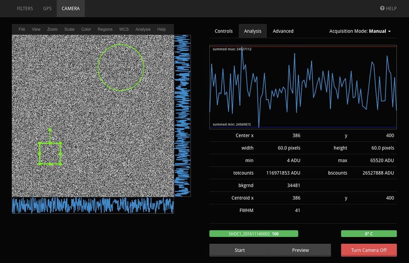
- It is also possible to select regions of the graph for further analysis, notably a real-time display of counts:
  (i) while taking images using the Preview mode, click on the "Analysis" tab in the camera GUI;
  (ii) Select the "Region" menu at the top of the js9 image display and select a box or circle or whatever shape you like;
  (iii) Click on the region (in the image) and the right side of the screen will show a plot of the counts within the region and numbers for various parameters below;
  (iv) The region can be moved and enlarged realtime, and the display updates accordingly;
  (v) Multiple regions can be added to the plot, and the display reports whichever region is current selected.
  (vi) The regions will continue to appear on the display under the "Controls" GUI tab.  Selecting "Region" -> "Delete Regions" will remove all of the regions shown on the frame.
Totcounts and bscounts
Totcounts are the total counts in the box region, while bscounts has the calculated background (see below) subtracted from the total.
Background and Noise
The background and noise are obtained from the outer 4 pixel-wide perimeter of the selected region. The background value is the median value of this area and the noise value is the RMS.
Centroid
The centroid is obtained by locating the brightest 9 pixel box and computing the centroid of the background subtracted data about this point.
FWHM
The FWHM is estimated from the image moments about the centroid, assuming a Gaussian distribution.
FITS Header Keywords
The FITS information is mostly drawn from the Andor camera. We have added additional keywords added to contain information on target (which can be entered by the user under the "advanced" tab in the web interface), the GPS settings, and from the telescope (when available -- currently only for the 74 inch). We have retained the raw state of Andor's keywords in order keep things as simple and straightforward as possible.
| Keyword and comments (example) | Notes |
|---|---|
| SIMPLE = T / file does conform to FITS standard | |
| BITPIX = 16 / number of bits per data pixel | |
| NAXIS = 3 / number of data axes | |
| NAXIS1 = 128 / length of data axis 1 | |
| NAXIS2 = 128 / length of data axis 2 | |
| NAXIS3 = 10 / length of data axis 3 | |
| EXTEND = T / FITS dataset may contain extensions | |
| COMMENT FITS (Flexible Image Transport System) format is defined in 'Astronomy | |
| COMMENT and Astrophysics', volume 376, page 359; bibcode: 2001A&A...376..359H | |
| BZERO = 32768 / offset data range to that of unsigned short | |
| BSCALE = 1 / default scaling factor | |
| HEAD = 'DU8201_UVB' / Head model | |
| ACQMODE = 'Frame Transfer' / Acquisition mode | |
| ACT = 1.11592 / Integration cycle time | |
| KCT = 1.11592 / Kinetic cycle time | |
| NUMACC = 1 / Number of integrations | |
| NUMKIN = 10 / Series length | |
| READMODE= 'Image ' / Readout mode | |
| IMGRECT = '1, 1024, 1024, 1' / Image format | |
| HBIN = 1 / Horizontal binning | |
| VBIN = 1 / Vertical binning | |
| SUBRECT = '897, 1024, 128, 1' / Subimage format | |
| DATATYPE= 'Counts ' / Data type | |
| XTYPE = 'Pixel number' / Calibration type | |
| XUNIT = 0 / Calibration units | |
| RAYWAVE = 0. / Rayleigh Wavelength | This seems to be irrelevant, since we are not taking spectra. |
| CALBWVNM= 0 / Wave calibration | This seems to be irrelevant, since we are not taking spectra. |
| TRIGGER = 'Internal' / Trigger mode | |
| CALIB = '0,1,0,0 ' / Calibration | |
| DLLVER = '2.97.30005.0' / Software Version | |
| EXPOSURE= 1.10916 / Total Exposure Time | |
| TEMP = 23. / Temperature | The CCD temperature. If the temperature is not yet stabilized, this will be -999.
Then UNSTTMP gives the unstabilized CCD temperature. |
| READTIME= 1.0E-06 / Pixel readout time | This corresponds to the 1, 3, 5, or 10 MHz readout amplifier. |
| OPERATN = 4 / Type of system | |
| GAIN = 0 / Gain | |
| EMREALGN= 0 / EM Real Gain | |
| VCLKAMP = 0 / Vertical Clock Amplitude | |
| VSHIFT = 6.5E-06 / Vertical Shift Speed | |
| OUTPTAMP= 'Conventional' / Output Amplifier | |
| PREAMP = 1. / Pre Amplifier Gain | This corresponds to the 1, ~2.5x, or ~5x gain setting.
See keyword SNTVTY or the camera spec sheets at http://shoc.saao.ac.za/Documents/iXon.X5982.SpecSheet.pdf and http://shoc.saao.ac.za/Documents/iXon.X6448.SpecSheet.pdf. |
| SERNO = 6448 / Serial Number | The serial number of the camera. |
| UNSTTEMP= -35.764 / Unstabilized Temperature | If camera temp is stabilized, this will be -999
and the temperature will be under keyword "TEMP". |
| BLCLAMP = F / Baseline Clamp | |
| PRECAN = 0 / Prescans | |
| FLIPX = 1 / Horizontally Flipped | |
| FLIPY = 0 / Vertically Flipped | |
| CNTCVTMD= 0 / Count Convert Mode | |
| CNTCVT = 1 / Count Convert | |
| DTNWLGTH= 500. / Detection Wavelength | A misleading keyword: the camera has no information about filters! |
| SNTVTY = 3.82 / Sensitivity | The e/ADU conversion. |
| SPSNFLTR= -5551 / Spurious Noise Filter Mode | A keyword that we are still trying to decipher. There are multiple camera
settings, and they result to values ofeither 0 or -5551. Setting 0 returns normal-looking data, but returns this -5551 value. |
| THRSHLD = 0. / Threshold | |
| PCNTENLD= 116 / Photon Counting Enabled | A keyword that we are still trying to decipher.
When this camera setting is "off" the value of 116 is listed in the header. When the setting is "on" the value is 0. |
| NSETHSLD= 0 / Number of Photon Counting Thresholds | |
| PTNTHLD1= 0. / Photon Counting Threshold 1 | |
| PTNTHLD2= 0. / Photon Counting Threshold 2 | |
| PTNTHLD3= 0. / Photon Counting Threshold 3 | |
| PTNTHLD4= 0. / Photon Counting Threshold 4 | |
| AVGFTRMD= 0 / Averaging Filter Mode | |
| AVGFCTR = 1 / Averaging factor | |
| FRMCNT = 1 / Frame Count | |
| PORTMODE= 0 / Port Readout Mode | |
| LSHEIGHT= 0 / Exposure Window Height | |
| LSSPEED = 0. / Line Scan Speed | |
| LSALTDIR= 0 / Alternating Readout Direction | |
| LSCTRL = 0 / Scan Speed Control | |
| LSDIR = 0 / Readout Direction | |
| FKSMODE = 0 / Fast Kinetics Storage Mode | |
| FKTMODE = 0 / Fast Kinetics Time Scan Mode | |
| USERTXT1= ' ' / User text | |
| USERTXT2= ' ' / User text | |
| USERTXT3= ' ' / User text | |
| USERTXT4= ' ' / User text | |
| DATE = '2015-04-17T14:34:28' / file creation date (YYYY-MM-DDThh:mm:ss) | |
| FRAME = '2015-04-17T14:34:28.000' / Start of Frame Exposure | This comment is incorrect. It is the time at the end of the first frame
for internal mode, and the time "start" is pressed for external triggering mode. |
| ESHTMODE= 0 / Electronic Shuttering Mode | |
| HIERARCH PREAMPGAINTEXT = ' ' / Pre-Amplifier Gain | |
| HIERARCH SPECTROGRAPHSERIAL = ' ' / Spectrograph Serial | |
| HIERARCH SHAMROCKISACTIVE = 0 / Shamrock is active | |
| HIERARCH SPECTROGRAPHNAME = ' ' / Spectrograph name | |
| HIERARCH SPECTROGRAPHISACTIVE = 0 / Spectrograph is active | |
| HIERARCH IRIGDATAAVAILABLE = 0 / IRIG Availability | |
| IRIGDATA= ' ' / IRIG Timestamp | This is the last keyword of those coming straight from the Andor Ixon camera. |
| AIRMASS = 'NA ' / The airmass (sec(z)) | Starting with this keyword, everything here and below has been
added in the SAAO software. Airmass comes from the TCS. |
| DATE-OBS= '2015-04-17T14:34:26.446239' / The time the user pushed start (UTC) | Note that during external triggering mode, this does not correspond to
any specific timing for the images. The camera started waiting at this time for a trigger from the GPS. |
| DOMEPOS = 'NA ' / The dome position | Read from the TCS. |
| ENVTEM = '26.65 ' / The average ambient temperature | This is the temperature on the plateau |
| FILTERA = ' ' / The active filter in wheel A | This should be a human-readable name for the filter in wheel A |
| FILTERB = ' ' / The active filter in wheel B | This should be a human-readable name for the filter in wheel B |
| GPS-INT = ' ' / GPS trigger interval (msec) | Set by the user on the GPS tab of the web interface. This is the
cadence at which GPS pulses are sent. Each pulse triggers a readout on the camera. |
| GPSSTART= ' ' / GPS start time (UTC; external) | Set by the user on the GPS tab of the web interface. This is the time
that the first GSP pulse was sent, which corresponds to the readout of the first GPS image. We typically toss the first two images in a GPS triggered sequence because the first is nothing (before the first pulse) and the second has slightly inaccurate timing. |
| HA = 'NA ' / The telescope hour angle | Read from the TCS. |
| INSTANGL= 'NA ' / The instrument angle | Read from the TCS. |
| INSTRUME= 'SHD ' / The SHOC instrument name | |
| INSTSWV = '1.0 ' / The SHOC software version | |
| OBJDEC = ' ' / Declination of object | From the user-entered information on the advance tab of the web interface. |
| OBJECT = ' ' / IAU name of observed object | From the user-entered information on the advance tab of the web interface. |
| OBJEPOCH= ' ' / Object coordinate epoch | From the user-entered information on the advance tab of the web interface. |
| OBJEQUIN= ' ' / Object coordinate equinox | From the user-entered information on the advance tab of the web interface. |
| OBJRA = ' ' / Right ascension of object | From the user-entered information on the advance tab of the web interface. |
| OBSERVER= ' ' / Observer who acquired the data | From the user-entered information on the advance tab of the web interface. |
| OBSTYPE = ' ' / Observation type | From the user-entered information on the advance tab of the web interface. |
| POSA = '7 ' / The slot position of wheel A | The numerical slot position of wheel A |
| POSB = '8 ' / The slot position of wheel B | The numerical slot position of wheel B |
| TELDEC = 'NA ' / The telescope declination | Read from the TCS. Currently only on the 74in! |
| TELESCOP= '40in ' / The telescope name | |
| TELFOCUS= 'NA ' / The telescope focus | Read from the TCS. Currently only on the 74in! |
| TELRA = 'NA ' / The telescope right ascension | Read from the TCS. Currently only on the 74in! |
| WHEELA = '011 ' / The ID of wheel A | The numerical ID of wheel A |
| WHEELB = '100 ' / The ID of wheel B | The numerical ID of wheel B |
| ZD = 'NA ' / The telescope zenith distance | Read from the TCS. Currently only on the 74in! |
| AIRMASS = 'NA ' / The airmass (sec(z)) | |
| HUMIDIT = '9.86 ' / The average humidity | |
| RELSKYT = '49.57 ' / The relative sky temperature (average cloud cov | |
| SEEING = 'Unknown ' / The curent seeing | |
| TMTDEW = '34.44 ' / Difference between current and dew-point temper | |
| WIND = '39.73 ' / The average wind speed | |
| END |
FITS Header Keyword Conversion
With the release of the new, web-based software there have been changes in the naming of some of the FITS keywords. The keywords are documented in the table below:
| Old Keyword | New Keyword |
|---|---|
| HIERARCH EMREALGAIN | EMREALGN |
| HIERARCH COUNTCONVERTMODE | CNTCVTMD |
| HIERARCH COUNTCONVERT | CNTCVT |
| HIERARCH DETECTIONWAVELENGTH | DTNWLGTH |
| HIERARCH SENSITIVITY | SNTVTY |
| HIERARCH SPURIOUSNOISEFILTER | SPSNFLTR |
| HIERARCH THRESHOLD | THRSHLD |
| HIERARCH PHOTONCOUNTINGENABLED | PCNTENLD |
| HIERARCH NOTHRESHOLDS | NSETHSLD |
| HIERARCH PHOTONCOUNTINGTHRESHOLD1 | PTNTHLD1 |
| HIERARCH PHOTONCOUNTINGTHRESHOLD2 | PTNTHLD2 |
| HIERARCH PHOTONCOUNTINGTHRESHOLD3 | PTNTHLD3 |
| HIERARCH PHOTONCOUNTINGTHRESHOLD4 | PTNTHLD4 |
| HIERARCH AVERAGINGFILTERMODE | AVGFTRMD |
| HIERARCH AVERAGINGFACTOR | AVGFCTR |
| HIERARCH FRAMECOUNT | FRMCNT |
A script is provided to convert back and forth between the two versions of the keywords. This is useful when working with a data pipeline that is still based on the old version of the keywords or to make old data compatible with a new data pipeline. The script can be used as follows from a command line terminal:
$ convert_keywords.py mydatacube.fits
This will convert the keywords in an old data cube to the new version. To convert the keywords back to the old version, run the script with the "revert" option:
$ convert_keywords.py --revert mydatacube.fits
In both cases the program will try to save the updated cube to a file with the same name, but postfixed with "_converted". So, "mydatacube_converted.fits" in the examples above. If the file already exists, you will be asked if you want to overwrite the file. If you do not want to overwrite the file you will be given the opportunity to enter a different file name. Multiple files can be converted at once by providing a list of them when running the program:
$ convert_keywords.py cube1.fits cube2.fits cube3.fits
NOTE: The conversion script makes use of Astropy. See the official documentation for installation instructions.
LED timing tests
This functionality should be available on the 74", the 40" and the new 1m. It has only been tested on the 74". The idea is to take a long, GPS-triggered data cube with SHOC at high cadence, while running the LED at 1 PPS (which has a longer pulse on the minute and can thus be used to test absolute timing accuracy).
- The dome and mirror covers must be OPEN for this test to work. (The GPS needs to get satellite signal, and the LED must be seen through the light path.)
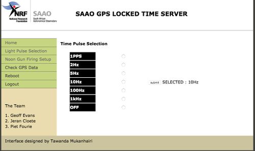
- There is an LED mounted in the telescope optical path that can be used to independently verify SHOC timing. Log into the following website:
http://10.2.55.5:4000/timepulse
Ask the Electronics standby for username and password. This website allows selection of LED pulses of different cadence (1, 2, 5, 10, 100 Hz and 100kHz), see the image below. Note that the pulse must be switched off when you are done, otherwise it will continue blasting photons into the telescope!
- Check that the LED is visible by turning on a pulse and seeing if it is apparent in the preview images. For example, take 0.2-s exposure and set the LED to 1 PPS, then look for increased counts/flashes on the display every 5th frame.
- To take a timing data cube:
- start the LED at 1 PPS
- in preview mode, increase the SHOC binning and readout speed to reach the desired exposure cadence (< 0.05s).
- set SHOC to external timing, select >=10000 frames, and start the GPS with repeated pulses at the chosen cadence
- REMEMBER TO TURN OFF THE LED PULSES WHEN DONE.
- Analysis: you are free to analyze your own timing data! Otherwise, an analysis pipeline has been written by Marissa Kotze and is supported by Carel van Gend. Carel can assist with data analysis.
- Download the SHOCpipeline.tar and PULSEtiming.tar software. Create a directory for the software (e.g. timingtests) and extract the software to that directory:
    mkdir timingtests
    cd timingtests
    tar -xvf ../SHOCpipeline.tar
    tar -xvf ../PULSEtiming.tar
- In the README file, follow the instructions on setting up iraf.
- Then make a further subdirectory for the testdata:
mkdir testdata
- Copy the data cube to this directory, and run the testPULSEtiming.py script:
    cd testdata
    python testPULSEtiming.py <SHOC fits file name>
- The software will examine the header, ask the user for confirmation of a few values, and then verify the timing. A report is printed out at the end.
In-depth Information
Characteristics and Properties
The specification sheets for the cameras, other manuals and documentation, can be found at http://shoc.saao.ac.za/Documentation.html .
Choosing an Observing Method
- BINNING: The plate scale is 0.076 and 0.163 "/pixel for the 1.9m without and with the focal reducer. It is 0.167"/pixel for the 1.0m without the focal reducer. The optimal binning is ~ 3 pixels per full width half maximum. The seeing conditions in Sutherland are typically > 1"; therefore, SHOC should usually be binned at least 2x2.
- For example, if the seeing is 2" and SHOC is mounted on the 1.9m telescope without the focal reducer, sources would be well sampled at a binning of 6x6.
- SUBFRAMING: The SHOC field of view is not large (1.3' and 2.8' on each side on the 1.9m without and with a focal reducer; 2.9' on each side on the 1.0m with a focal reducer). Subframing is typically only used if the cadence needs to be increased.
- MODE: For most observations, the mode should be selected that allows the desired cadence with the lowest read noise. Start by setting 1 MHz Conventional mode in the optimal binning, and type 0 in the exposure time -- the time will default to the minimum allowable (and the cadence will be displayed). If the cadence is too slow, either subframe or select 3 MHz Conventional mode. The EM mode should only be used in cases of experienced observers who understand both the risks and the noise vs. signal payoffs.
- GAIN: The three gain settings correspond to different electron/ADU conversion values and effect dynamic range. They are slightly different from camera to camera. The standard options for conventional modes are as follows:
- Mode...................... Approx. Gain setting................... Approx. Electrons/ADU
- 1 MHz Conv....................1, 2.5, 5....................................... 4, 1.5, 0.7
- 3 MHz Conv...................1, 2.5, 5....................................... 10, 4, 1.8
User's troubleshooting guide
Camera Issues
- Camera won't switch on: If the camera display times out when trying to switch on, you will need to restart the services. To do this:
- Open a terminal. This is available from the top menu or side menu of the thin client in the warm room. If the web browser is full screen, push 'F11', and you should then see the top menu bar. Once the terminal window appears, ssh to the instrument by running the command
ssh shoc74in@shoc74in.suth.saao.ac.za
or
ssh shoc40in@shoc40in.suth.saao.ac.za
When prompted for the password, use the password for the 74in or 40in user.
- In the terminal, type
restart_services
You will again be prompted for the password. The various services comprising the instrument will then restart. This lasts a few seconds a few seconds.
- Return to the web browser, and reload the page, then try to start the camera again.
- It may be necessary to restart the services a few times before you can start the camera.
- Acquisition doesn't start: Check on the GPS tab that the trigger signal has been activated. If it has, but the camera is still not taking images, try stopping the camera, resetting the GPS trigger to a time in the near future, and try again. Sometimes, it appears that the GPS trigger signal is not being sent (despite the software reporting that it is). The current acquisition should be stopped and restarted (because when the acquisition is started, the time the POP signal will start is recorded and will apear in the fits headers - so stopping and starting the acquisition will ensure that the correct POP time is used). Note that the index willl be incremented when doing this. To avoid this, you can rewind the increment by 1, in the advanced tab. Make sure you have no data that will be overwritten.
- Acquisition doesn't finish: Sometimes it appears that the camera does not ever leave the acquiring state (despite all images in the kinetic series having been obtained). It may in this case be neccessary to restart the server, manually edit the FITS files to include the filter and timing informations, and to then copy them to their final destination. The server may be restarted running the command "restart_services" from a terminal. The data is spooled to a directory under /data/spool/, based on the date, the sequence number and the time the acquisition started. In this directory is the data file, data.fits, and file containing other acquisition parameters, info.txt. The latter may be used to update the FITS header. The procedure is as follows:
- Rescue your data using the data rescue utility, as described in the section Rescuing Data.
- Run the command to restart the webserver, as described above in the subsection "Camera won't switch on".
- Return to the web browser, refresh the page, turn the camera back on, and continue with your observing. If the camera is non-responsive, run the restart_services command again.
- IMPORTANT:
- Check that the file number is correct --- look at the Advanced Tab, and the Start Index should be that for the next file. Currently, for the Phase 1 software, this number seems to be the same as the file you just saved from spool and you will likely need to increase it by one to avoid overwriting.
- The filter wheel needs to be reinitialized. Go to the filter wheel tab, click the initialize button under the active wheel(s).esh the camera tab in the browser window
- Camera tab is frozen: Occasionally (often at the start of the night) the first acquisition causes the camera tab to become unresponsive and 'freeze up'. The solution to this is to restart the services, as described above, then refresh the browser window and try again to restart the camera. This may need to be repeated several times before the camera starts.
- Camera overheats: Should the camera over heat (this normally results from the air outlets being blocked), an alarm will sound from the camera. Unfortunately no indication or reason for the alarm will be given on the control software. In the case of this happening please shut the instrument down and contact electrical support immediately. THE CAMERA MAY NOT BE USED WHILE THE ALARM IS SOUNDING.
GPS Issues
- The GPS time is not valid: If the GPS reports that the timing is not valid, check that it is able to see at least a few satellites, and that the signal quality is acceptable. Click on the Receiver Status button on the GPS tab, and a pop-up should appear, displaying the signal quality of the visible satellites. If each signal quality bar is zero, check that the dome is open; the antenna can't detect the satellites if it's closed. If there are a number of satellites visible, each with a reasonable signal, you might need to wait for a while for the GPS to rgister this and for the time to become valid. Normally this happens quite quickly, but for reasons we don't entirely understand, sometimes this can take five or ten minutes.
It may also help to put the GPS into dynamic mode. Usually the GPS is set to operate in static mode, where the known position of the telescope is used. In dynamic mode, the GPS will first locate itself before getting a lock on the time. It may be that doing this will help to get a lock on the time.
To put the GPS into dynamic mode, or to return it to static mode, use the command line interface described below. (One can also return the GPS to static mode by doing a "restart_services" call.
To use the command line interface:
- Fire up a terminal
- $ ssh <user>@<shocndisbelief|shocnawe>.suth.saao.ac.za
- $ shoc-gps-cli
- The commands in the cli are help, status, pop, mask, bias, timing_mode and location. Use "help <command>" for more information.
- The timing_mode option makes the GPS use static or dynamic mode.
- The status option prints out all the current status reported by the GPS. If the command line tool reports an error while updating the status, simply try again until it works.
- type "q" to exit the interface
Dealing with large FITS files
When taking very large data cubes, the file sizes may grow unmanageably large. On older 32-bit systems, FITS files were automatically truncated at 2GB and rolled over, but on the new 64-bit systems we use, this does not happen. Consequently, very large FITS files may be generated. To cope with these, there is a utility called split_fits.py. This script prompts for the name of a FITS file to split, and the number of chunks into which it should be split. It then splits the large file into this number of smaller files. The FITS header is identical in each of the resulting files.
The script split_fits.py is installed on both astro.cape and astro.suth, in the directory /usr/local/saao/bin. To run it, type
split_fits.py
then when prompted enter the filename and number of chunks to produce. The output files are put in the same directory as the input file.
Rescuing Data
N. B. It is NOT normally necessary to run the data rescue script described below; the problem we had with the interface freezing up and acquisitions not being completed is now solved.
Under normal operation, the system automatically updates the FITS cube header with supplementary information (filter, external trigger parameters, telescope pointing information etc.) and the moves the cube to the permanent (for the night) storage area. From time to time, it may be necessary to do this manually, using the rescue_data.py tool. In particular, if the system has frozen at the end of an acquisition, but before fixing the header and moving the data file, it will be necessary to perform this procedure. This procedure does NOT need to be done when stopping an acquisition; only if the interface hangs and you cannot do anything do you need to run this script.
- The procedure is to open a terminal and find your data in the spool directory on the instrument computer. It's stored in a directory named /data/spool/<CCYYMMDD><index>.<HHMMSS> (where index is the index, CCYYMMDD is the date and HHMMSS is the time the acquisition started). For example, /data/spool/201503250002.141026/ .
- Caution: the date is the actual date valid when the acquisition was begun. If this was after midnight, the date will be incremented by one day. This is NOT the same as for the final FITS files; the final FITS file names are based on the date which was valid at the start of the night. Bear this in mind if you go back and try to rescue data which was acquired on previous night!
- The procedure is done by using ssh to connect to the SHOC host computer:
ssh shoc74in@shoc74in.suth.saao.ac.za
or
ssh shoc40in@shoc74in.suth.saao.ac.za
When prompted for the password, use the password for the 74in or 40in user. Then go to the directory containing the spooled files:
       cd /data/spool
       ls -l
       cd <CCYYMMDD><index>.<HHMMSS>
       ls -l
- There should be files named data.fits and info.txt
- The info.txt file contains the supplementary information.
- Run the rescue utility: type
sudo rescue_data.py
and then answer the questions as prompted. You'll be prompted for a password, use the password for the user you logged in as.
- The telescope is the name of the telescope being used; either 40in or 74in.
- The instrument will be one of shocnawe (sha) or shocndisbelief (shd). These are used to create the directory and filename in the /data directory. The directory will be of the form /data/<telescope>/<lowercase_instrument>/<YYYY>/<MMDD>, and the file of the form <instrument>_<YYYYMMDD>.<index>.fits. From this, the instrument name can be determined. At the moment, SHA is the SHOC instrument mounted on the 74inch and SHD is on the 40in.
- You will be prompted for an index to use. NB: make sure there is no existing file with the same index that will be overwritten The script will scan the target directory and list the existing files. Choose and index which isn't used(one option is to use an index like 3a , if index 3 exists). In other words, if files such as SHA_20150403.0004.fits and SHA_20150403.0005.fits, choosing either index 4 or 5 will result in that file being overwritten. If you choose as index 4a or 5a, the files will not be overwritten.
Technician's guide
IMPORTANT: If a SHOC machine is swapped out and installed on a different telescope, the website aliases (shoc74in and shoc40in) and data storage paths will be *incorrect*. Please notify the IT standby person before trying to use them. Currently, shocnawe is tied to the 74in and shocndisbelief is tied to the 40in.
Mounting SHOC
- The SHOC box should be mounted at the base of the telescope, and the camera should be mounted below the filter wheel box.
- With the power OFF, connect the following cables:
- computer to camera operation (thick, white cable)
- computer to camera trigger (thin back with gold SMB)
- camera power (black)
- GPS antenna (BNC from telescope into the GPS in the SHOC box)
- network cable (ethernet from back of SHOC box)
- SHOC box power (standard three-prong cable from back of the box)
- the filter wheel to the computer
The power must be off when disconnecting and reconnecting cables.
- To power up:
- (1) Turn on power to the outlet where the SHOC box cable is plugged
- (2) Turn on power switch at the back of the SHOC box.
- (3) Press the computer power button on the front of the computer.
Testing the components
- Once the machine has booted, fire up a browser and point it at http://shocnawe.suth.saao.ac.za:5000/ or http://shocndisbelief.suth.saao.ac.za:5000/.
- In the filterwheel tab:
- Check that the filterwheel(s) can be initialized and moved by selecting the initialize button, then selecting a different filter(s) and moving the wheel(s).
- In the GPS tab:
- Check that the time is valid (it will read "valid" in green). (Note: the time will NOT be valid if the GPS antenna cannot see the sky. The dome must be open for the GPS to see satellites.)
- Check that POP settings can be made:
- Set mode to repeat.
- Pulse width should 10 microseconds (default)
- Start date should be set or selected to be today's date.
- Start time should be set to some seconds or a min in the future, localtime.
- Repeat interval can be your choice: this is just a test value, something like a few hundred millisec is appropriate.
- Click the apply button .
- The status should change to pending, and at the chosen time, should change to activated. Make sure to switch off the POP signal again by clicking stop.
- Make sure to close the dome before trying the camera tests, or else the images could be saturated.
- In the camera tab:
- Check that the camera can be switched on (press "turn camera on")
- Check that the cooler is working (the temperature should drop)
- Check that the camera is reading out: confirm the setting is full frame, conventional mode (the default) and press "preview". Images should appear every ~ 1.2 sec. Once confirmed that images are coming through, press "stop".
- Switch the camera off again (press "turn camera off").
Configuring the SHOC computer (not the web interface!)
To access the SHOC computer, ssh into it from a terminal on your local machine or tablet (e.g. ssh ccd@shocnawe.suth.saao.ac.za or ssh ccd@shocndisbelief.suth.saao.ac.za).
- Ensure GPS location settings are correct in /home/ccd/programming/shoc/shoc/instruments/gps/gps.py:
- after sshing, move into the directory: cd /home/ccd/programming/shoc/shoc/instruments/gps/
- open the file using a viewer: vi gps.py
- Use the up and down arrows to view each line of the file. Check that the location settings for Sutherland are active (not commented with a '#') and that the settings for Cape Town are commented (i.e. are preceded by a '#'). To remove a character type x . To add a character type a followed by the character to add, then hit esc to stop inserting. To exit, type :wq .
- Edit service settings using the file /etc/init/shoc-camera.conf (the filepaths need to have the correct telescope and instrument names):
- after sshing, move into the directory: cd /etc/init/
- open the file using a viewer: vi shoc-camera.conf
- Use the up and down arrows to view each line of the file. Change the telescope name to the name of the currently used telescope: 74in or 40in. The instrument name should already be set to sha or shd (for shocnawe or shocndisbelief) and the log level should be info (not debug). In the editor, to remove a character type x . To add a character type a followed by the character to add, then hit esc to stop inserting. To exit, type :wq .
- To enact any changes made during configuration, restart all services:
- Under /home/ccd/programming/shoc/bin/, type the following: ./restart_services
Switching the SHOC computer to a new telescope
Notify the IT standby person, so that the DNS records can be altered - they should use the information below.
Normal Setup
| Name | Type | Content | TTL |
|---|---|---|---|
| shocnawe.suth.saao.ac.za | A | 10.2.2.89 | 86400 |
| shocndisbelief.suth.saao.ac.za | A | 10.2.2.88 | 86400 |
| shoc40in.suth.saao.ac.za | CNAME | shocndisbelief.suth.saao.ac.za | 360 |
| shoc74in.suth.saao.ac.za | CNAME | shocnawe.suth.saao.ac.za | 360 |
| shoc1m.suth.saao.ac.za | CNAME | shocndisbelief.suth.saao.ac.za | 360 |
The shoc computer should be reachable by an alias containing the telescope name. Usually shoc74in is an alias to shocnawe, and shoc40in is an alias to shocndisbelief. If, e.g. shocndisbelief is mounted on the 74inch telescope, the alias shoc74in should be changed to point to shocndisbelief.
IT should ONLY change the CNAME record. The A records should NEVER change. Even if only one of the instruments is being moved to another dome, BOTH records must be switched or DNS resolution will be intermittent. Example of a switched DNS setup:
Instrument switched setup
| Name | Type | Content | TTL |
|---|---|---|---|
| shocnawe.suth.saao.ac.za | A | 10.2.2.89 | 86400 |
| shocndisbelief.suth.saao.ac.za | A | 10.2.2.88 | 86400 |
| shoc40in.suth.saao.ac.za | CNAME | shocnawe.suth.saao.ac.za | 360 |
| shoc1m.suth.saao.ac.za | CNAME | shocndisbelief.suth.saao.ac.za | 360 |
The above setup was always the normal setup but now the shocndisbelief machine is in the 1m dome (old 30Inch). The shocndisbelief will no longer be in the 40inch and will not move around, only the shocnawe machine will move between the telescopes. Therefore the setup below is what needs to change when the shocnawe is moved.
Note that the shocnawe now points to shoc40in.suth.saao.ac.za. If it is configured like this, that means the shocnawe machine is in the 40inch. When it is moved, only change the 40 to 74 like below:
From
| Name | Type | Content | TTL |
|---|---|---|---|
| shoc40in.suth.saao.ac.za | CNAME | shocnawe.suth.saao.ac.za | 360 |
To
| Name | Type | Content | TTL |
|---|---|---|---|
| shoc74in.suth.saao.ac.za | CNAME | shocnawe.suth.saao.ac.za | 360 |
Note When You SSH After CNAME Change
Note: This change will result in a warning if someone tried to SSH into the machine - this is safe to accept.

ssh ccd@shoc40in.suth.saao.ac.za
Warning: the ECDSA host key for 'shoc40in.suth.saao.ac.za' differs from the key for the IP address '10.2.2.89'
Offending key for IP in /Users/simon/.ssh/known_hosts:283
Matching host key in /Users/simon/.ssh/known_hosts:317
Are you sure you want to continue connecting (yes/no)? yes
Possible CNAME Changes
With the CNAME setup below, both the shocndisbelief and shocnawe can be connected in the new 1m. Please ask the IT standby person to help you with this DNS setup. At this moment only the shocnawe will be moved between the 40inch and 74inch. The shocndisbelief is in the 1m and will not be moved between the 40inch and 74inch.
How It It Configured Now
| Name | Type | Content | TTL |
|---|---|---|---|
| shoc1m.suth.saao.ac.za | CNAME | shocndisbelief.suth.saao.ac.za | 360 |
Can Be Added If Required
| Name | Type | Content | TTL |
|---|---|---|---|
| shoc1m.suth.saao.ac.za | CNAME | shocnawe.suth.saao.ac.za | 360 |
Run Shocboxswitch.sh When Shoc Is Moved Between Domes
Run the script shocboxswitch.sh. The default option reverts to the standard mapping between shoc computers and telescopes. If the default is not chosen , you'll be prompted for the name of the telescope the shoc computer is being mounted on.
Unmounting SHOC
- Before physically unmounting the instrument from the telescope, the SHOC control computer should be powered down. To do this:
ssh ccd@shocnawe.suth.saao.ac.za
or
ssh ccd@shocndisbelief.suth.saao.ac.za
Then
sudo shutdown -h now
- Once the operating system has powered down, the power may be switched off and the instrument removed from the telescope.
Technician's Troubleshooting guide
- SHOC computers have two disks, a solid state drive to which data are spooled and a hard drive which runs the system. If there are concerns about the disks, you can verify mount points:
- At the command line, type the command 'mount'. The solid state disk should be mounted on /data/spool, while the spinning hard disk should be mounted on /data.
- Time is not valid:
- Check that the antenna cable has been connected to the SHOC GPS on the box.
- Check that the antenna has access to the sky (i.e. the dome is open)
- Check that the location settings are correct. Click on 'receiver status' in the GPS tab and look at the latitude and longitude. The Sutherland Latitude is ~32 22 S while Cape Town is 33 56S. If the location is not corrrect, then the GPS will not find satellites and the correct location needs to be updated as described in the Configuring SHOC section.
- Camera is in an inoperable state:
- Restart the services by sshing into the SHOC computer (see Configuring SHOC section):
- change into directory /home/ccd/programming/shoc/bin and type the following: ./restart_services. It may be neccessary to do this a few times.
- If that does not work, under /home/ccd/programming/shoc/bin type the following to stop and start in separate steps:
- Restart the services by sshing into the SHOC computer (see Configuring SHOC section):
- ./stop_services
- ./start_services
- If prompted for the password, it is the same as that for the ccd user.
- Worst case scenario, when restarting the entire computer seems like an appropriate option:
- ssh into the SHOC computer (see Configuring SHOC section)
- type the following: sudo shutdown -h now
- The computer will shutdown. To power back on, someone must MANUALLY go press the button on the front of the SHOC computer.
* If, for whatever reason, you decide to open the SHOC computer case, you MUST USE ELECTROSTATIC PROTECTION. The computer components, especially the PCI card, are electrostatically sensitive. The computer should be placed on a grounding mat and a grounding wriststrap should be used before anything is touched.
